Depends; we ideally want it at/below the XO point, so is about right for a recommended 1.3 kHz min..Impedance peak of HF108R is at over 1 kHz. Would it be better to be at lower freq?
Why would you want it below the XO point? Because of the higher impedance itself (which could be fixed) or some other effect we cannot fix?Depends; we ideally want it at/below the XO point, so is about right for a recommended 1.3 kHz min..
Below the first resonance the output becomes limited much more quickly, the impedance of the driver and horn is a combination, for example Legis has used the HF108 on a Yuichi A-290 clone horn which loads the driver much lower and allows it to have more usable output.Why would you want it below the XO point? Because of the higher impedance itself (which could be fixed) or some other effect we cannot fix?
There is a bit of a mismatch between the Celestion and 15" driver, the 15" is becoming more directive and the waveguide is losing directivity, there is no perfect match. The trade off can be seen in the Asathor. Drivers like the BMS 4550 have more xmax and a lower resonance allowing them to cross lower. That would lower the directivity mismatch but it would still be there.
With an active crossover you can try it either way and see if there is an audible difference.
Pi speakers that were mentioned earlier also use a larger driver with a smaller horn crossed higher in some models
https://www.pispeakers.com/Pi_Speakers_Info.pdf
I didn't see any specifications or charts on the pi-speaker site.
Here is how even the dispersion can be with a 70 w 1.4" CD + a 15" driver. See page 3 of SP2-XT spec. Peavey brags about 6 db dispersion, but -3 db dispersion according to the charts is +-22.5 deg from center 500 hz to 16 khz, and +- 10 deg vertical (pointed down at the heads of the audience). Crossover 1200 hz.
That speaker had high efficiency, 101 db 1w1m. I owned a pair, stolen 2020. I'm trying to duplicate in an ugly box that has no pawn shop value.
Attachments
https://www.pispeakers.com/Measurements/I didn't see any specifications or charts on the pi-speaker site.
The directivity of the Peavey is strange, the DI is pretty flat through most of the range but the horizontal and vertical are all over the place at certain points. The Pi H290C or the Celestion 9040 are smoother and more even overall.Here is how even the dispersion can be with a 70 w 1.4" CD + a 15" driver. See page 3 of SP2-XT spec. Peavey brags about 6 db dispersion, but -3 db dispersion according to the charts is +-22.5 deg from center 500 hz to 16 khz, and +- 10 deg vertical (pointed down at the heads of the audience).
One doesn't need 90 deg directivity unless one is standing 2 m from speakers 2 m apart. I admired the -3 db +- 22.5 deg response horizontal and +-10 deg response vertical measurements: Which cover sitting or standing from 3 m away or farther. Mr. Kamphuy's room is 4 m long. I walk around my music room from 2.5 m to 5 m away, sideways 3.6 m, and the sound didn't change. Not much different 11 m away in the kitchen through 2 double door openings.The directivity of the Peavey is strange, the DI is pretty flat through most of the range but the horizontal and vertical are all over the place at certain points. The Pi H290C or the Celestion 9040 are smoother and more even overall.
That chart is 6 db response anyway, which would be an annoying change. The polar plots have 6 db circles and the 3 db point is about half of one division.THe 4 pi response curve which is 15" + horn looks worthy of copying. But response only plotted out the 40 dg, which is all you need anyway.
Last edited:
The Peavey has a 90 degree horizontal beamwidth over much of it's range. It's not about the angle you need to cover the area of listening, more the direct to reverberant ratio. A 90 x 40 horn will sound different to a 60 x 40 even within the area where both are very even. This comes down to personal preference.One doesn't need 90 deg directivity unless one is standing 2 m from speakers 2 m apart.
Beamwidth by convention is taken at the -6dB point, important to know when comparing the coverage angles listed by manufacturers.That chart is 6 db response anyway, which would be an annoying change.
As a result of the crossover and fs remarks, I read part of the loudspeaker cook book. It mentions 'alignments'. As far as I could tell, non of the (unassisted?) alignments require an enclosure the size of the original Calpamos. What's going on?
The carefully arranged roll-off is messed up when I incorporate the baffle step. So, why bother with alignments?
Also the impulse respons (transients) seems to be something to consider. Is it? Is there any software to show it and some text that talks about it and the influence on the sound? I guess I could figure out the impulse respons myself, but why make mistakes if something else gives the correct answer?
I've been tumbling down mount Stupid for the last few days...
Attachments
Always wanted to know.... better to crossover below the F3 baffle step point or above ?
What if the F3 Baffle step middle point is near the Helmotz frequency of the room (around 200/300 hz most often ?) and the loudspeaker is 1 meter from the front wall ? Should i care with such a 15" woofer ?
What if the F3 Baffle step middle point is near the Helmotz frequency of the room (around 200/300 hz most often ?) and the loudspeaker is 1 meter from the front wall ? Should i care with such a 15" woofer ?
^^ "perfect" impulse response is not possible with passive crossovers but you can do it with FIR filters, with DSP. Some try and make 1st order passive crossovers which get close, but this kind of systems won't have too much SPL capability. It is basically something that single fullrange driver is doing but with two or more fullrange drivers and I don't see the point. Just use FIR if there is need to perfect the impulse response and call it a day.
Ability to choose baffle step is a trick one can use to juggle the design so that a passive crossover doesn't become overly complex but again it usually comes with compromises, like having wide baffle which requires large roundovers to prevent baffle edge diffraction which is lot of work to do. With DSP it doesn't matter too much because the cost is constant no matter how many filters you need to use.
Crossover filter, aligments, whatnot, have names so that they can be discussed but there is no reason to use particular alignment or filter unless your system you have built demands for it. All that matters is the end result, acoustic output of the whole system. Measurements would include effects of the structure, like the baffle step, and how your transducers perform etc. From real measurements of real system you are able to "perfect" a crossover in simulator, without ever knowing the names of filters or alignments you ended up using. What ever is the "perfect". Some people want to use some particular named filters just because, or do passive xovers with 3 components just because, or do what research have found would win blind listening tests, or what ever is the interest of the day. Some keep possibilities open and use what ever works or what ever is at hand without being overly concerned about it. All that matters is the acoustic output, the stuff you listen to, pressure variations in the room, not xo alignment names.
I propose DSP just because it doesn't limit the system like passive does, for example the baffle width thing. I preserve right to change my mind for passive xovers some day, if I can come up with a speaker design that works with passive xo and beats the stuff I'd made with DSP previously 🙂 Point is, there is no such thing as perfect speaker and the xo is just part of any speaker that has to be there (excluding some edge cases), no need to go religious about it although you can if you wanted to because personal delight. For now, you could just skip it and concentrate thinking what you want to have in the end, the big picture. All the rest are just details behind it and you don't have to know them all yet.
edit. or did you mean box alignments, for the bass?😀 Alright, count in room dominating the whole response where you have the alignment carefully planned out. I've reasoned that having bass box in the ballpark, problem free as a speaker, is reasonable goal. Response at listening spot is pretty much just about the room and position of the stuff in room. You can have carefully planned 303.3 litre enclosures to gain 3dB more at some 33Hz, and then there might be room gain that boosts it another +13dB more and you have to then tune it down with EQ, and the effort was for nothing 🙂 Just don't sacrifice mid range performance with box alignment and you are good I think. This is particularly important with 2-way speaker since the bass is what plays all the mids as well and there is nothing you can do to fix the mids other than rebuild / emergency patch the box (alignment). Bass response however, can be and is best cured by adding more boxes, sub woofers.
Last edited:
I've seen Mr. Kamphuys room plan. It seems to me as if putting the speakers 1 ' or less from the long wall eliminates the baffle step problem. http://speakerdesignworks.com/bafflestep.html say this about wall placement :
Speakers shoved up againt the wall don't need baflle step compenation for lost bass. Speakers 1 to 1.3 m into the room do, need all 6 db of it.
I plan to test my 2 way speakers outside in an open field, but backed up against a cinder block wall of my garage. Similar to placement in my room where speakers are 1/3 m from a 1" thick plaster wall 3.2 m high & 3.7 m long. So I should get plenty of bass boost from the wall. Speaker designer that plan to install at the front of a stage (bars, auditoreums) have to provide more bass on a 2 way. BSC in a single mid-bass. What bands actually do in pop music is buy a separate sub box and boost the **** out of it.
I listen to music 14 hours some days, 7 days a week, and running stereo through ONE amplifier strikes me as the enviromentally mature thing to do . That means, after prototyping with 2 amps and graphic equalizers (instead of DSP) I need to design & install a passive crossover. For my purposes, no sub is necessary. SP2-XT experience demonstrated it to me; 54 hz -3db response is fine for classical music. Response falls off about 20 db/octave below 50 hz, but organ 32' pipes and low 3 notes of the piano sound pretty good with speaker 1' from a hard wall.
Last edited:
Yeah it depends on frequency of course, long wavelengths get bounce from the wall(s) as do the shorter ones and what matters is how you perceive it at the listening spot. I had small full range speakers some years ago without any baffle step compensation and they were great for what they were, enjoyed a lot when the good positioning was found and sat in the sweet spot. It is matter what one wants to trade-off, hence always think about the big picture before details.
I'm not exactly sure how the transition against wall happens, but with simple image-source reflection method one can calculate that about 1 foot to front wall reflection point would be 2 feet as round trip towards listening position. Perfect cancellation with direct sound would happen when this is half wavelength, so 4 feet would have deep null. Any longer wavelength than this would get gain from the reflection without issues with nulls as it would add constructively to direct sound. 4 feet is about 280Hz. Reasoning while looking at diffraction simulations it looks like that if baffle is roughly as wide or wider as distance to wall, baffle step compensation is not needed.
I'm not exactly sure how the transition against wall happens, but with simple image-source reflection method one can calculate that about 1 foot to front wall reflection point would be 2 feet as round trip towards listening position. Perfect cancellation with direct sound would happen when this is half wavelength, so 4 feet would have deep null. Any longer wavelength than this would get gain from the reflection without issues with nulls as it would add constructively to direct sound. 4 feet is about 280Hz. Reasoning while looking at diffraction simulations it looks like that if baffle is roughly as wide or wider as distance to wall, baffle step compensation is not needed.
Last edited:
The Calpamos uses an EBS (Extended Bass Shelf) type of alignment, a big box with a low tuned port. The 15PR400 would rolloff much higher without it.As a result of the crossover and fs remarks, I read part of the loudspeaker cook book. It mentions 'alignments'. As far as I could tell, non of the (unassisted?) alignments require an enclosure the size of the original Calpamos. What's going on?
It's not really messed up just needs to be compensated. The in room response from 400Hz down becomes increasing room dominant, with EQ there is a good argument for not worrying too much about alignments. Without EQ they become the only option available to try and control the low end response.The carefully arranged roll-off is messed up when I incorporate the baffle step. So, why bother with alignments?
If you are struggling a good place to start is Floyd Toole's Sound Reproduction, that covers a wide range of material from directivity to room response etc.
Putting speakers nearer to walls is often a good option when EQ is available to compensate. I do that myself. You do have to be mindful that shoving the cabinets directly against the wall is very rarely the best place for them due to the boundary dip ending up in the worst frequency range to have one.Speakers shoved up againt the wall don't need baflle step compenation for lost bass. Speakers 1 to 1.3 m into the room do, need all 6 db of it.
Graphic attached from Floyd Toole's Sound Reproduction
Attachments
^ yeah.. On the other hand if we simplify and assume the speaker is small enough to have omni radiation at some low frequencies. These low frequencies would not show much difference if speaker was rotated or tilted some. On higher frequencies though, the radiation towards specular reflection point on the wall would have increasingly more output to it with more tilt/rotation and possibly worse looking graphs could result for the bandwidth between the speaker being omni and "beaming". Assuming there is more output towards forward direction and less to the back, and varying amounts to the side in between. For ideal dipole there would be total cancellation 90 degrees to the side and could be toe-in with no interference seen at inspection point.
In general, if inspection point changes, the path length difference changes between direct and reflected sound a bit and the interference due to wall shifts a bit in frequency. There would be less interference on frequencies that have less radiation towards the reflection point. On low frequencies this is hard to achieve but there is no need to if got close enough the wall. Higher frequencies directivity is easy and even automatic without trying. Hence problematic bandwidth for front wall reflections is between, on the mid range 🙂
Here are some additional info for the interested without going into details like perception and taking account other boundaries in room but trying to connect the reflection into practical things. Thought to make new thread for this kind of stuff but I'll just post it here:
I found it very interesting how much attenuation is needed in order to lessen the effect of reflection, the interference. Here is series of attachments with ideal direct sound and likewise ideal reflection whose path length is ~2 feet longer, roughly situation if the speaker was 1 foot deep pushed against front wall. Red line is direct sound and green the reflected sound response (both ideal flat). Interference measured at 3 meters is the black line.
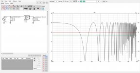
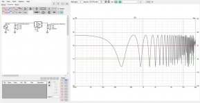
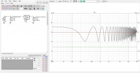
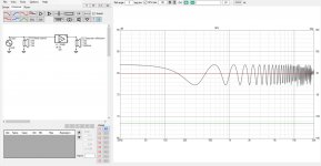
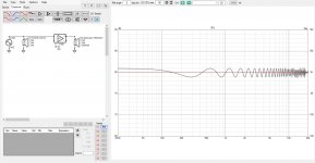
In this case, inspected from 10 feet away, it takes about 17dB of attenuation to get the interference to +/- 1dB!
Notice there is constructive and destructive interference (black line above and below the red). To effectively get rid of "a interference dip" both need to be cancelled. Hence narrow band filters won't make too much difference to the peaks or dips in the interference. Here 17db notch at 300Hz with Q of 2 and 1. The destructive interference is almost gone, but the constructive interference both below and above still remains and there is just wide platoe dip.
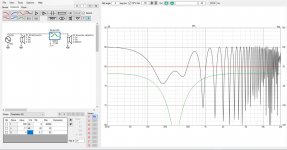
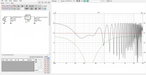
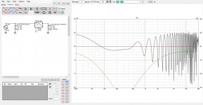
How these numbers relate to real world speakers? Attenuation due to baffle to back side of speaker, to specular reflection point on front wall, seems to be about this magnitude (10-20dB) roughly from baffle step and up. Waveguides can exceed this easily on frequencies they have influence on but this is also above baffle step. Waveguides can help limit radiation to other boundaries though, like the side walls, floor and ceiling. MTM can have strong attenuation to a (vertical) reflection points but it is only about octave wide. Dipole/ OB stuff can have very deep very wide bandwidth attenuation to first reflection points.
Peace 🙂
In general, if inspection point changes, the path length difference changes between direct and reflected sound a bit and the interference due to wall shifts a bit in frequency. There would be less interference on frequencies that have less radiation towards the reflection point. On low frequencies this is hard to achieve but there is no need to if got close enough the wall. Higher frequencies directivity is easy and even automatic without trying. Hence problematic bandwidth for front wall reflections is between, on the mid range 🙂
Here are some additional info for the interested without going into details like perception and taking account other boundaries in room but trying to connect the reflection into practical things. Thought to make new thread for this kind of stuff but I'll just post it here:
I found it very interesting how much attenuation is needed in order to lessen the effect of reflection, the interference. Here is series of attachments with ideal direct sound and likewise ideal reflection whose path length is ~2 feet longer, roughly situation if the speaker was 1 foot deep pushed against front wall. Red line is direct sound and green the reflected sound response (both ideal flat). Interference measured at 3 meters is the black line.


In this case, inspected from 10 feet away, it takes about 17dB of attenuation to get the interference to +/- 1dB!
Notice there is constructive and destructive interference (black line above and below the red). To effectively get rid of "a interference dip" both need to be cancelled. Hence narrow band filters won't make too much difference to the peaks or dips in the interference. Here 17db notch at 300Hz with Q of 2 and 1. The destructive interference is almost gone, but the constructive interference both below and above still remains and there is just wide platoe dip.


How these numbers relate to real world speakers? Attenuation due to baffle to back side of speaker, to specular reflection point on front wall, seems to be about this magnitude (10-20dB) roughly from baffle step and up. Waveguides can exceed this easily on frequencies they have influence on but this is also above baffle step. Waveguides can help limit radiation to other boundaries though, like the side walls, floor and ceiling. MTM can have strong attenuation to a (vertical) reflection points but it is only about octave wide. Dipole/ OB stuff can have very deep very wide bandwidth attenuation to first reflection points.
Peace 🙂
Last edited:
Any sections in particular?If you are struggling a good place to start is Floyd Toole's Sound Reproduction, that covers a wide range of material from directivity to room response etc.
Not really unless there is something in particular you are struggling with. The 3rd edition is much improved and expanded on the earlier ones and more easily read from start to finish. Whilst there is some opinion and experience related, in general it is a distillation of the most relevant research from someone who is good at explaining.Any sections in particular?
it takes about 17dB of attenuation to get the interference to +/- 1dB!
Let's see if my math checks out. Never really got the feeling for dB's, even though a lot of my colleagues use them all the time for radar stuff. I guess I should divide by 20 (10 doesn't get me close):
10^(63/20) / 10^(80/20) = 0.141...
10^(81/20) / 10^(80/20) = 1.122...
So it's about right, right? Constructive interference should result in 1.122, which is the direct sound (1.0) + the reflected sound (-17dB = 0.141).
Indeed. I'm reading it.The 3rd edition is much improved
And I found a video of a presentation by Earl Geddes where he states something like (and I paraphrase): "Don't bother about the enclosure (alignment). It's all determined by the room." I guess that matches with quite some comments here. So just don't mess up big time, but no need to tweak the hell out of it?
Perhaps, not good at math either, just looking at the graphs 😀 Assuming your math is correct, error / difference in your calculation to my approximation is explained with some attenuation in the path length difference (there is some extra attenuation to the inspection spot, from the further sound source) as well as accuracy of my eyeballing.
- Home
- Loudspeakers
- Multi-Way
- Efficient 2-way

