The power up was done using a dim bulb tester and power was only on for less that 30 seconds, just long enough to assess the behavior of the dim bulb, which did not dim, and the LEDs, all of which lit but were dimmer that previously. Those two observations have been my main reason for believing something is amiss with the right channel pcb. Is there a test I can do with a multimeter or an LCR to confirm the integrity of the IRFPs while they are in the board?IRFPs not being firmly bolted to heatsink - exact and certain recipe for having them fried
go figure
Also I completed the picodumb mod by installing the LEDs but I am still having the problem I just described on startup. All the solder joints are clean and not shorting, all wires are where they should be. I am kind of afraid to leave the amp turned on for any length of time to take measurements while this channel is connected for fear of doing further damage. I'm kind of up a tree. Not sure what I should be looking for at this point.
Thanks Mike for the desoldering tip on using a puller. I improvised on the idea by using a small thin zip tie and it is sooooo much easier than trying to juggle pliers or tweezers! I also learned that with care I could avoid the need to clean out the hole by melting the old solder and inserting the leg of the LED assembly. It works because I left the legs long and they are relatively easy to handle.Check the bias across R1 the .56 resistor to see what it is. You can also check the voltage on each side of the resistor you just installed. Check the resistors you installed to make sure they are the correct value, check for a cold solder joint and check continuity to the next point on the board touching the resistor lead.
When you are adjusting the DC offset, you are adjusting the bias of the 2nd mosfet to match the first one. So the problem is likely in the part of the circuit that ties to the 2nd mosfet closest to the transformer.
When desoldering, I use something like this to grab the leads:
https://www.testequity.com/product/...3oZPU2tKenbULQq7P3kO-OwicjQvsJYxoCaOwQAvD_BwE
Grab one side of the resistor, melt the solder on that side and pull the resistor end out. If the resistor is mounted too close to the board, you can melt the solder on one side and push the lead through the hole. This would give you enough room to grab the resistor. With that being said, I elevate all of my resistors off of the board a bit so that I can pull them, reuse, easily grab to test etc.
When you are ready to clear the hole, add more solder to the solder pad, melt it with the gun, move the gun out from in front of the hole while doing your best to still heat the solder, use the solder sucker. The holes on these boards have pads on both sides and throughout the inside of the hole which makes it a little tougher to suck all of the solder out which is why you need the heat. I keep my soldering gun at around 625F for removing solder. About 525F for desoldering.
Best of luck!
first thing is - always work on one channel only, at least when starting with setting procedure of new amp
when you're done with first channel, you can leave it connected to PSU and start working on second channel
now - no way of testing IRFP in situ, except for shorts ....... and even with them pulled from pcb, you can practically test them just for shorts with DMM
for more informative testing, you need simple matching jig and external PSU - even laptop supply is enough and in most cases most critical link to have is solved
now - F6 is simple ; you can test everything without mosfets on pcbs; "everything" means - confirming biasing voltage for mosfets - practically checking which voltage span you're having for both trimpots varying from end to end, having probes applied to (unpopulated) mosfet Source pin and its Gate pin
if you can confirm something as 0V to +5V voltage span, you're good - just set them to close to 0V and proceed
mount mosfets, take care of torque , take care of having zillion of zillions ohms between mosfet (mid pin) body and heatsink
place one Voltmeter across upper or lower Source resitor
place second voltmeter across output qand GND
flip da switch, fiddle iteratively with trimpots as long is needed to get desired Iq and 0 DC Offset at temp equilibrium
pretty much - F6 i s- as I said - simple ...... patience and systematic work is enough to build it, who needs knowledge and mileage
use the camera; post picture what you did, whenever you feel insecure; Boyz will chime in and you'll get it for cheap and easy
Thank you Zen, I will have to read your message several times to make sure I understand everything and even then we’ll probably be back to you with questions.
The frustrating thing is that I had the amp working and it actually sounded pretty good but I couldn’t get the bias numbers right so began by changing the 10 K resistors to 3.3 K, And things seem to go downhill from there. Now I am not sure what’s working and what is not. My only real red light is that the dim bulb is not getting dim and staying fairly brightly lit. Do I dare leave the amp on and do some voltage measurements while running through the dim bulb? Is it possible that nothing is damaged and I’m just misinterpreting the significance of the dimbulb testers behavior?
The frustrating thing is that I had the amp working and it actually sounded pretty good but I couldn’t get the bias numbers right so began by changing the 10 K resistors to 3.3 K, And things seem to go downhill from there. Now I am not sure what’s working and what is not. My only real red light is that the dim bulb is not getting dim and staying fairly brightly lit. Do I dare leave the amp on and do some voltage measurements while running through the dim bulb? Is it possible that nothing is damaged and I’m just misinterpreting the significance of the dimbulb testers behavior?
bulb tester is usable when testing unloaded PSU , to be sure that nothing is going BigBAdaBoom
once when amp is half-set or fully set, PSU is loaded enough that amp is drawing significant juice from wall and thruogh bulb tester, so you have voltage sag across bulb and amp is voltage starved...... being somewhere in voltage limbo
now - you must - after changes you made - dial back biasing trimpots, so biasing voltage for mosfets is not big enough to open them
try deducing where to measure resistance to confirm that you dialed in pots all the way back, then you can use dim bulb again for unloaded amp, then remove it and proceed with setting
post your reference schm and I'll tell you where to put ohmmeter probes to set trimpots for first step
and, when posting that schematic, indulge me - write again exact changes which you made for biasing circuit
Bruce, please continue as ZM suggested. I hope you can figure out how to dial the P1/P2 pots down so the mosfets aren't conducting current.
If you're having trouble and assuming you are still using a 5.1V zener or 3 LEDs giving about 6V, then one thing that should work is to count the number of turns on your pots and simply set them to roughly mid point. The Vgs values won't be close to zero but for those zener or LED values they should be low enough that the mosfets shouldn't conduct much current. And if you are unsure then it is probably safer than turning the pots all the way up or down and getting them in the wrong direction.
If you're having trouble and assuming you are still using a 5.1V zener or 3 LEDs giving about 6V, then one thing that should work is to count the number of turns on your pots and simply set them to roughly mid point. The Vgs values won't be close to zero but for those zener or LED values they should be low enough that the mosfets shouldn't conduct much current. And if you are unsure then it is probably safer than turning the pots all the way up or down and getting them in the wrong direction.
Okay, I really appreciate yours and @Dennis Hui help here, so what follows is, I hope, what you asked for along with my recap of what I think your are guiding me to do. Along with two questions to help clarify.bulb tester is usable when testing unloaded PSU , to be sure that nothing is going BigBAdaBoom
once when amp is half-set or fully set, PSU is loaded enough that amp is drawing significant juice from wall and thruogh bulb tester, so you have voltage sag across bulb and amp is voltage starved...... being somewhere in voltage limbo
now - you must - after changes you made - dial back biasing trimpots, so biasing voltage for mosfets is not big enough to open them
try deducing where to measure resistance to confirm that you dialed in pots all the way back, then you can use dim bulb again for unloaded amp, then remove it and proceed with setting
post your reference schm and I'll tell you where to put ohmmeter probes to set trimpots for first step
and, when posting that schematic, indulge me - write again exact changes which you made for biasing circuit
F6 Trouble Shooting
Schematic:
AMP


Modified (PicoDumb Mod)


Potentiometer setting:
These are Bourn 20 turn 5k pots as in 6L6’s list of materials. Upon startup I learned that turning them counter clockwise allowed more current to flow (decreased resistance). So clockwise increases resistance. You can tell when you reach the end of their range by a small clicking sound they make while being rotated.
Current Situation:
Left Channel is configured as shown in the first Schematic.
Bias (voltage across 0.47 ohm R2) 0.2 v
Offset (taken at speaker leads) .05 v
Right Channel taken after installing 3.3K resistors but before adding LEDs as in 2nd schematic.
Bias (voltage across 0.47 ohm R2) 0.52 v
Offset (taken at speaker leads) 4.71 v
Then one of the slow blow 2.5 A fuses on the AC inlet blew at startup after doing some measurements. The amp was not
on the dim bulb tester at that time.
After fuse replacement the power supply and the left channel seem to behave normally when started with dim bulb tester but when the right channel is added the bulb stays brightly illuminated and I have not allowed the amp to remain on for more than a few seconds. So no further measurements.
Procedure going forward:
If I understand your instructions correctly.
1. Disconnect left channel
2. Remove IRFP 240 mosfets from right board.
3. Power up right board (can be off heatsink) from power supply and confirm operation of pots (measuring resistance up and down) and take voltages across R2 or at mosfet source pin and gate pin and at speaker terminals (bias and offset respectively)
If there are other problems on the board that I have not detected is there a list of expected voltages that I can compare against to pin down the source of the problem?
4. When all is good re-install mosfets, attach to heatsink
5. Startup on dim bulb tester and if all looks as it should move off dim bulb and fine tune bias and offset.
Sound like the plan?
Questions:
Can I expect the 3 LEDs to light when the mosfets are removed? Despite careful effort , they did not light during my brief startups following installation and might need to be reversed. But right now they may not be lighting because of another as yet un-identified problem in the circuit.
The Mosfet gate pin is the middle one, I believe? How can I be sure which is the source pin on Q1 and Q2? Is the source the one closest to the resistor R1 and R2 respectively?
Pics:
Here are some pics of the board under consideration:


Hi folks, long time no see...
Back on post #999 I had fried my A channel and after a long layup (a lot has gone on, but basically I was tidying the loft last week and thought I really should have another look at it...).
So, I have a functioning power supply 25v on the rails. B channel is working, 0.5v Bias and 0v offset (sounded sweet last night for a brief mono celebration).
Channel A is still defeating me tho. I replaced the MOSfets before I put it away 4 years ago. Today I reflowed all the joints and it all looks tidy, no signs of stray solder or any dirt on the keratherm patches. Set the pots to mid point.
I started up with the bulb tester in place. A brief glow and it died back to nothing. The Led was on. No volts on R2 and the offset. Having re -read the thread I figured I may need a few turns on the Bias pot - the offset increased a bit, so I flip flopped between the two pots but the Bias refused to rise - after about 6 turns (I wasn't really counting) of the bias then reduce the offset, the bulb came back on. I switched of and checked the MOSfets for hot, both cold.
I had checked the resisters with my DVM and they were all good i.e reading about their stated value. R2 is still reading the right value. I did a quick check before fiddling with the pots and confirms zero on R1 too.
Could it be something stupid like putting the zeners in the wrong way (the silver bars are at the pointy ends of the triangle on the board like the B channel)? could the MOSfets be dud? The led being lit and offset but no bias has confused me
I'm kinda stumped again, but I really want to get this up and running. Too dark for pictures and not sure what to measure so I'm planning a beer before having a look in the daylight tomorrow.
Any pointers would be dead handy. Thanks in advance, Al
Al,
You cannot perform the bias procedure with the bulb tester in place.
I suggest you dial the pots back down and then power up only channel A with the bulb tester. If all goes well, the bulb will light and then dim.
If the channel passes the bulb test, power down and then move the bulb tester. Now power up again and measure the voltages across the zeners Z1 and Z2. If they are at or near their zener voltage, then they are ok, and you can start the biasing procedure.
Edit: The bar on the zener should be at the line/pointy end of the triangle on the silkscreen so what you have should be correct.
Last edited:
Thanks Dennis - success! I might have not clipped my DVM in very well and I think the pots were a long way off... Currently warming up and stablising - Yay!Al,
You cannot perform the bias procedure with the bulb tester in place.
I suggest you dial the pots back down and then power up only channel A with the bulb tester. If all goes well, the bulb will light and then dim.
If the channel passes the bulb test, power down and then move the bulb tester. Now power up again and measure the voltages across the zeners Z1 and Z2. If they are at or near their zener voltage, then they are ok, and you can start the biasing procedure.
Edit: The bar on the zener should be at the line/pointy end of the triangle on the silkscreen so what you have should be correct.
Thanks again (and to 6L6, Zen Mod, Fabrice63). I'm biasing to 0.5 and going to have a listen
")
Really cant thank you guys enough...
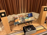
A topless glamour shot for you, sod the early night!
Spotify through the DAC into the amp, volume on the computer. FH3s with CHP drivers (not on optimum position and will epically fail WAF, but the boss is away). The bass is amazing 🤩 currently mellowing out with The Dead.
A bit of cable tidying and rebias to nearer 0.60 and fit the posh feet. I will post in the completed builds. 👍🤩😎😁
Attachments

Bruce, you should also test the mosfets since they weren't properly attached to the heatsink and you had a blown fuse.
Your step 3 above should be by measuring the voltage across the two outer holes for the gate and source pins. But before that you need to fix the string of LEDs to that they light up and that you measure about 5-6 volts across them.
And you need to turn down both P1 and P2 so that the voltages across the gate/source pin locations are low (close to zero).
Thanks Dennis, I will get started on this in the next day or so but right now we are having some good weather here in NJ and I need to get outsideBruce, you should also test the mosfets since they weren't properly attached to the heatsink and you had a blown fuse.
Your step 3 above should be by measuring the voltage across the two outer holes for the gate and source pins. But before that you need to fix the string of LEDs to that they light up and that you measure about 5-6 volts across them.
And you need to turn down both P1 and P2 so that the voltages across the gate/source pin locations are low (close to zero).
Meanwhile regarding the Mosfets, I thought I understood Zen mod to say you basically can't test them. Is there something I can do when I remove them? Basically all I have in the way of test equipment is a DMM and an LCR meter.- Home
- Amplifiers
- Pass Labs
- F6 Illustrated Build Guide