I knew I was combining terms in there somewhere.What you had in #3729 were monolithic bridges. What you have in #4137 are bridges with discrete diodes.
A couple potential reasons for the voltage change are different winding ratios between the transformers and/or a higher voltage drop through rectification.
Seems like a tweak of the bias, and you're ready to keep the covers on. Thanks for posting all the progress and questions. What a fantastic reward for sticktoitiveness. Two fantastic amps. Congrats!
.
.
.
.
So, whatcha gonna build next?

Yeah, I'm wondering if the secondary voltage is a littler higher on the Hammonds or if the voltage drop on the monolithic bridges is a little less. Or combination of the two. Luckily, the right channel still has the old PSU so I can take some measurements.
Still have to install the new PSU in the right channel:

Then install the 2nd set of F6 boards to try balanced:

And if that doesn't work (i.e. too much offset I can't adjust for or don't like the bass response) then throw some F5 boards in to try:

And I'm still contemplating a pair of F4s but would need a voltage source.
While I'm contemplating the F4s, going to upgrade the crossovers in my Halcyons (still needs some big coils):

Then after all that, with all the channels of amplification I'll have, contemplating active crossovers on the halcyons.
Lots to do, so little time.
Last edited:
While awaiting the replacement mosfets for my right channel I completed the Pico dumb mods on the still populated and presumably undamaged left channel. Despite all the good advice I received I must have got something wrong because a fuse blew when I first powered up.Please see attached for the pinout of IRFP240. The gate and source are the two outer pins.
View attachment 1043864
I used the Right channel with it's vacant Mosfet holes to confirm that full clockwise rotation of the pots yielded 0 v at the gate and source pins. I then zeroed the pots on the populated left channel. When I power it up, using the dim bulb, it began with 0 v across the 0.47 ohm resistor and at the speaker terminals, leds were all on and the dim bulb came on with the power and quickly went out. I adjusted the bias carefully up to 0.5 v across the 0.47 resistor. Voltage across the speaker terminals however was 5.0v and the dim bulb was glowing moderately bright and the LEDs all looked dimmer. Rather than begin to open up the offset pot I shut down.
Can you tell me if this looks normal? I'm kind of concerned that the offset mosfet was damaged when the fuse blew previously and that opening up the voltage on the offset pot may cause further damage. I thought that the offset voltage across the speaker terminal would only be a few tenths of a volt. Don't want to do any more damage (or pull any more Mosfets) than I have to
you can't bias an amp (increasing Iq from 0 to desired value_) with bulb tester in circuit
current taken from mains is rising, bulb is eating voltage, amp is getting lesser and lesser voltage as you dial Iq up
back up with trimpots to 0 Iq position, remove bulb tester, proceed with setting procedure
current taken from mains is rising, bulb is eating voltage, amp is getting lesser and lesser voltage as you dial Iq up
back up with trimpots to 0 Iq position, remove bulb tester, proceed with setting procedure
Do what ZM wrote. Set P1 and P2 back to their zero position. Now check that the bulb tester passes. If this test passes, remove the bulb tester,
since it's been mentioned a few times that you cannot do the bias procedure with the bulb tester in place.
Please note that you should adjust P1 and P2 in tandem. You shouldn't turn one on all the way to get 0.5V across 0.47R resistor before adjusting the other one.
When you get a bit of voltage across the 0.47R, you will see some DC offset and you should adjust the other pot to trim down the DC offset. Alternate adjustments of the two pots to slowly bring up the bias while keeping the DC offset low.
Glory be it worked! I was sure that I had blown another MOSFET. Dennis, Your method of going back-and-forth and gradually raising both ppots was the key and it is different than the original instructions given by 6L6 which was to set the bias to 0.5v and then zero out the offset.Do what ZM wrote. Set P1 and P2 back to their zero position. Now check that the bulb tester passes. If this test passes, remove the bulb tester,
since it's been mentioned a few times that you cannot do the bias procedure with the bulb tester in place.
Please note that you should adjust P1 and P2 in tandem. You shouldn't turn one on all the way to get 0.5V across 0.47R resistor before adjusting the other one.
When you get a bit of voltage across the 0.47R, you will see some DC offset and you should adjust the other pot to trim down the DC offset. Alternate adjustments of the two pots to slowly bring up the bias while keeping the DC offset low.
also initially, I was a bit too blasé about thinking that you could power up and just tinker around to get the levels right, and then after I blew two fuses I became overly cautious. I bet it wouldn’t shock either of you to hear that back when I was a student I would occasionally get looks from instructors indicating that I had found ways to make mistakes that they had never seen before
Hello,
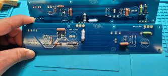
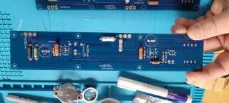
I'd just like to ask a question before I proceed. You'll notice in these pics that some of my resistors are much larger than it appears the board planned for. I had to get creative bending. I guess I ordered a higher wattage than I needed to. Aside from not being necessary, is this an issue. Im trying to learn as I go but I'm just painting by numbers right now. I was successful with a TU-8500 and then B1 Nutube preamp which emboldened me. This is certainly a bit more technical, but I figured if I'm careful I'll be alright.
Thanks in advance
Attachments
Hey folks, a quick update and another thanks. finishing this has made be disproportionately happy this week 😁
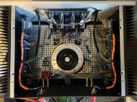
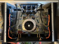
I’ve tidied some cables, but I need to address the transformer and that was a pain to fit. I might talk to a pal to help make me can or a couple of L brackets to stand it up and shield it. I can hear a buzz if I stick my ear over the case and the same tone coming through the drivers. it’s not loud and you have real close to notice. The cables outside are a rats nest too. So a bunch of thing to address in slow time.
Bias is even, 0.604/0.00 on both sides. It spent about 10 hours at 0.500/0.00 last week and the increase in bass is amazing since raising it. Well not just bass, it’s all bigger. The heat sink is about 42 degC but I’m getting mixed temps on the 2nd pin so loathed to increase the bias at the mo, until I get a better way to measure temp (I’ve got heat transfer paste on the thermistor).
I really am super stoked about it. My good lady has passed comment too, so results and plaudits all round.
Hats off to papa and the gang on here.
Attachments
Yes. The (unmarked) R2’s… left hand side under the cap at the back and on the right hand side the green resistor against the cap at the back.Congratulations on your build Alistair.
Just want to check one thing: You mentioned a bias of 0.6V, can you confirm that's 0.6V across the 0.47 ohm source resistor?
Attachments
Last edited:
1.3A bias current is a reasonable place to start. After using the amp for a while, you can try increasing the bias to 1.8A. The “standard amount“ is where you feel comfortable with heatsink temperature.
I run mine at 1.8A and +/– 26V rails. The green LED voltage ref tweak is intended to allow the amp to rach stable thermal equilibrium a little faster at higher bias.
I run mine at 1.8A and +/– 26V rails. The green LED voltage ref tweak is intended to allow the amp to rach stable thermal equilibrium a little faster at higher bias.
I might have to look at the green LED mod, but tbh I might just listen as is. It’s in a sub par set up in the corner of my office and it’s blowing me away…1.3A bias current is a reasonable place to start. After using the amp for a while, you can try increasing the bias to 1.8A. The “standard amount“ is where you feel comfortable with heatsink temperature.
I run mine at 1.8A and +/– 26V rails. The green LED voltage ref tweak is intended to allow the amp to rach stable thermal equilibrium a little faster at higher bias.
That said, now I’ve got the bug, I’m thinking about adding a linear power supply and volume pot to my ACA’s and then doing a pair of F6 mono blocks…
I should probably go and listen to some tunes 🤪
What temperatures are you seeing on the mosfets and 2nd pin?1.3A bias current is a reasonable place to start. After using the amp for a while, you can try increasing the bias to 1.8A. The “standard amount“ is where you feel comfortable with heatsink temperature.
I run mine at 1.8A and +/– 26V rails. The green LED voltage ref tweak is intended to allow the amp to rach stable thermal equilibrium a little faster at higher bias.
I haven’t measured the temperature. I can place my hands on the heatsinks indefinitely, though they are quite warm. I use ceramic insulators under the Mosfets (very good thermal coupling) and aluminum L brackets between the bottom of the heatsinks and the baseplate. The chassis is from China and is 3.5U by 400mm deep. I bought it before shipping charges went crazy.
Hi folks,
Had my F6 up and running since last weekend (biased beautifully to about 0.6v, 0v offset) with the transformer simply plugged and resting outside the chassis while waiting for an L bracket to arrive. The amp sounded amazing (so much better than the Prima Luna I've been listening to...).
Yesterday, upon receiving the L bracket, I drilled the baseplate and fixated the transformer vertically after trimming its secondary leads. Things went very bad from there: turning the amp on I noticed the PSU and amplification LEDs kinda wavered strangely before shutting off. Then went back on very brightly... Before shutting back off. Now the amp won't turn on (guessing the fuse is out, have to confirm tonight).
While the amp was on, I managed to check voltages across PSU rails and things looked rather normal. AC on these was a good bit higher than when I measured the PSU unloaded, which seems like expected behaviour.
My intuition tells me it's a short, do you have any recommendation as to how to start the troubleshoot? First time builder here.
Thanks in advance 🙏
Arthur
- Home
- Amplifiers
- Pass Labs
- F6 Illustrated Build Guide