This building is based on a revised BG1 layout. I have some more mod to do so it can be use either with Bjt (To264/TO3P) either with mosfet (To247/To264) with or witout driver stage for mosfet=> a kind of universal BG1 pcb
NOTE to BYRTT : i don't forget your advices on BC i will place a via in the middle of the track between 550/5560, but with this pin config we must tight them together befor soldering on board=> no possibility to bent after.
NOTE to BYRTT : i don't forget your advices on BC i will place a via in the middle of the track between 550/5560, but with this pin config we must tight them together befor soldering on board=> no possibility to bent after.
Attachments
Last edited:
hi Borys,
Would advice to go with or without driver stage for one pair? In your config. have swap Bjt in bias servo by IRF540 as ever do?
Same PCB (with or without) can be use i think by omitting bjt driver transistor and change 4r7 by a jumper but that goes to collector bjjt and no to base. Also zener must be added.
Marc
Marc
I would do the pcb for BJT version + add some space for 2 zeners.
It would be universal for toshiba mosfets and BJT's. Two driver stage can be fitted in (my example) or one of them can be bypassed with jumpers.
For bias servo (with Toshiba mosfets) you can use bjt transistor - has similar tempco as 2sj201/2sk1530 (i have putted some pic before in this topic).
IRFP output version should have irf transistor as bias servo.
Regards
Borys,
Even a single bjt for bias regulator is overcompensation for the 1530/201.
Please have a look at the first page of the PDF in post 123. I'be tried a few vbe multiplier options to get this OPS temperature stable.
Greetz
http://www.diyaudio.com/forums/solid-state/198209-amp-design-subwoofer-wideband-duty-13.html
Borys,
Even a single bjt for bias regulator is overcompensation for the 1530/201.
Please have a look at the first page of the PDF in post 123. I'be tried a few vbe multiplier options to get this OPS temperature stable.
Greetz
http://www.diyaudio.com/forums/solid-state/198209-amp-design-subwoofer-wideband-duty-13.html
Yes I know that is overcompensated but still better than with irfp (bias was dropping to 50-60% of nominal value). I am using nearly same circuit for compensation mosfets with bjt transistor --> 2x1n4148 or better 1.2V lm reference diode - improvement aprox 10-15% (but stil overcompensated).
I think it is not a big problem, you can set the cold amp at 130mA and after it heats up bias will be around 100mA - imho should be fine.
I am on Holliday in one week and will begin BG1 enclosure work. It will be made with MDF painted for "body" and veneer for front. The enclosure size is 33(L)x31(deep)x25(H) cm Under 5 project drawing :
1 - front view (maplpe veneer)
2 - front view without front plate
3 - front view without front panel+Trafo and soft start compartiment
4 - open side view
5 - top view
The architectur is about the same as the Nmos 200 i build (see picture) witout rectifier and caps rank in the middle replaced by capacitance multiplier direct under amp board on heatsink. Heatsink that will be used for BG1 are the same : 230x200x40mm with 10mm base
Marc
Very nice!
I would do the pcb for BJT version + add some space for 2 zeners.
It would be universal for toshiba mosfets and BJT's. Two driver stage can be fitted in (my example) or one of them can be bypassed with jumpers.
For bias servo (with Toshiba mosfets) you can use bjt transistor - has similar tempco as 2sj201/2sk1530 (i have putted some pic before in this topic).
IRFP output version should have irf transistor as bias servo.
Regards
=> Under
Attachments
Hi Marc
That final build is very nice and artistic, this field i think for everyone is personal taste and is what is beautifull for diy'ers. But you hit me a little bit because i certain years had Kawasaki MC, and the limegreen they used for bikes back then looks like your cabinet.
By the way have you listened SQ after the CM PSU ?
Good holiday Marc, Ricky
Hi Marc
That final build is very nice and artistic, this field i think for everyone is personal taste and is what is beautifull for diy'ers. But you hit me a little bit because i certain years had Kawasaki MC, and the limegreen they used for bikes back then looks like your cabinet.
By the way have you listened SQ after the CM PSU ?
Good holiday Marc, Ricky
Thanks BYRTT,
i don't yet have CM PSU, parts are under way...
Marc
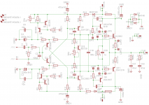
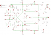
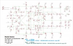
borys, Idefixes and others DIY-rs please take a look at these circuit if these correct how it drawn.
I want to compare with my old Darlington circuit which does not have CSS only a zener diode.
I do like the front end of these circuit.
So these will use power darlingtons and instead BD139 I will use darlington device there to.
The reason I want to test these topology with darlington
Way back 2 decade ago I built up the discrete darlington I used some Motorola power device (like MJL) with BD2## driver.
The result was very upsetting compare to the cheap BDW83C/84C darlington.
Also we tested with LATfet and the darlington much better in bass area
Probably the Sanken and better driver better in the circuit now but we only know if we test it.
Gabor
Attachments
Last edited:
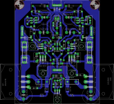
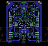
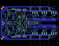
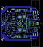
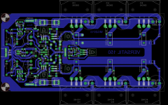
Another PCB ver of BG1-BJT, ready to connect with PSU. Some pics:
bc550c/560c
bd139-16/140-16
2sc4793/2sa1837
mjl3281/1302
In a few days I will try this amp, how works and how play music")
Also, I'll do some measurements on the scope.
BR,
Boban
An externally hosted image should be here but it was not working when we last tested it.
An externally hosted image should be here but it was not working when we last tested it.
An externally hosted image should be here but it was not working when we last tested it.
An externally hosted image should be here but it was not working when we last tested it.
An externally hosted image should be here but it was not working when we last tested it.
bc550c/560c
bd139-16/140-16
2sc4793/2sa1837
mjl3281/1302
In a few days I will try this amp, how works and how play music
Also, I'll do some measurements on the scope.
BR,
Boban
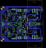
Another PCB ver of BG1-BJT, ready to connect with PSU. Some pics:
An externally hosted image should be here but it was not working when we last tested it.
An externally hosted image should be here but it was not working when we last tested it.
An externally hosted image should be here but it was not working when we last tested it.
An externally hosted image should be here but it was not working when we last tested it.
An externally hosted image should be here but it was not working when we last tested it.
bc550c/560c
bd139-16/140-16
2sc4793/2sa1837
mjl3281/1302
In a few days I will try this amp, how works and how play music
Also, I'll do some measurements on the scope.
BR,
Boban
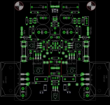
Very well hidden bias transistor, nice board!! Looking forward to hear your opinion about the amp. Regards
Gabor
All looks fine - go ahead with your layout.
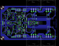
Another PCB ver of BG1-BJT, ready to connect with PSU. bc550c/560c
bd139-16/140-16
2sc4793/2sa1837
mjl3281/1302
In a few days I will try this amp, how works and how play music
Also, I'll do some measurements on the scope.
BR,
Boban
Hello Boban
If you can please replace those Samwha capacitors, one of the worst caps on the market, not for audio.
You have done a really nice job, that PC board, the other parts and the circuit deserve some decent capacitor.
About the Samwha not just my experience also Sakis and others wrote the same.
Panasonic FC cheap and it would do the job very well.
Thank you borys
Cheers Gabor
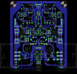
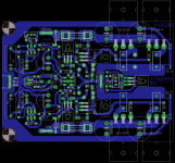
VERSATIL Family : TO3P/TO247/TO264 devices can be used
Either BJT or mosfet according modifications on schematic (place are on PCB)
-VERSATIL 50 : 1 pair OD +/-35Vdc rail 88x102mm
-VERSATIL 100 : 2 pair OD +/-50Vdc rail 88x123mm
-VERSATIL 150 : 3 pair OD +/-50Vdc rail 88x150mm
Marc
Either BJT or mosfet according modifications on schematic (place are on PCB)
-VERSATIL 50 : 1 pair OD +/-35Vdc rail 88x102mm
-VERSATIL 100 : 2 pair OD +/-50Vdc rail 88x123mm
-VERSATIL 150 : 3 pair OD +/-50Vdc rail 88x150mm
Marc
Attachments
Last edited:
Versatil MT Family :
Same schematic and profile only with MT200 case device for Sanken
-VERSATIL MT50 : 88x107mm
-VERSATIL MT100 : 88x145mm
-VERSATIL MT150 : 88x183mm
Marc
Same schematic and profile only with MT200 case device for Sanken
-VERSATIL MT50 : 88x107mm
-VERSATIL MT100 : 88x145mm
-VERSATIL MT150 : 88x183mm
Marc
Attachments
VERSATIL Family : TO3P/TO247/TO264 devices can be used
Either BJT or mosfet according modifications on schematic (place are on PCB)
-VERSATIL 50 : 1 pair OD +/-35Vdc rail 88x102mm
-VERSATIL 100 : 2 pair OD +/-50Vdc rail 88x123mm
-VERSATIL 150 : 3 pair OD +/-50Vdc rail 88x150mm
Marc
Thanks Idefixes for sharing your versatil pcbs
Have you considered connecting C7/C8 return to GND instead of GND1 ? This could be the cherry on the cake?

Fab
Thanks Idefixes for sharing your versatil pcbs
Have you considered connecting C7/C8 return to GND instead of GND1 ? This could be the cherry on the cake?
Fab
Could you explain me the advantage to do this. When i look at schematic C7/C8 are after R18/D8 and R17/D7 so for me direct in first input stage PSU area that's why i connected them to GND1.
In practice connecting C7/C8 to GND is quite difficult to do without redesigning completely the whole input area.
Marc
Edit : in TSSA layout the same area is connected to GND to and not GND1...will take a look but explain me why...
Last edited:
- Home
- Amplifiers
- Solid State
- FET-hex explendit amplifier