Just tu confirm, BG1 is working with fets OK. I have soldered 2sj201/2sk1530, replaced gate resistors with 100R and putted two zeners. Bias is setting up ok. At the moment I have as bias transistor bd139 and cold amp setted up to 45mA bias is dropping to 38mA after 10min playing of music (so is not too bad).
Idefixes
If you will made a room just for two zeners on the board there would be posibility to solder BJT or mosfets at output.
Sound with toshiba mosfets has really rich top end, worth every penny I have spent on them.
Nice work borys

This reminds me when I changed my Hiraga super class A output for these excellent mosfets....

Fab
Hi Marc
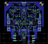
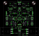
A little nit pickin about input stage, i say because i see you later in evening shall do room for rectifiers.
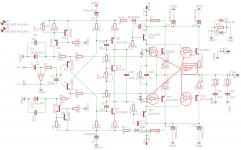
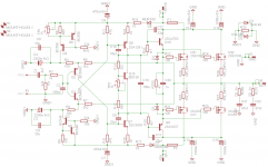
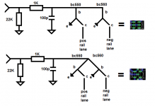
It is about when single ended signal hit bc550/bc560 and go paralell (spread) to neg/pos lane, here bend basis leg on each bc550/bc560 against each other and put through same hole on pcb, because as is now signal hits one device first and then next device and in theori will be feed down the lane in timedomain before last device.
Just small thing BR Ricky
A little nit pickin about input stage, i say because i see you later in evening shall do room for rectifiers.
It is about when single ended signal hit bc550/bc560 and go paralell (spread) to neg/pos lane, here bend basis leg on each bc550/bc560 against each other and put through same hole on pcb, because as is now signal hits one device first and then next device and in theori will be feed down the lane in timedomain before last device.
Just small thing BR Ricky
borys
It is not possible to leave out one stage like at the HEXfet or LATfet version?
I know it works but sometimes an extra stage would leave the fingerprint in the sound.
Sometimes less is better..
Probably it would be simpler if the HEXfet layout will be modded so we can use the Toshiba mosfets.
These is my humble opinion only, I do not want to be smart.
Greetings Gabor
By the way I want to adopt your amplifier to power darlington so I can make A-B test between these and my old design.
Idefixes
Small update to make life easier. My toshiba mosfets are from Y group so need bit higher Ugs - but no change in biasing circuit is required to set the bias.
===> under
Attachments
borys
It is not possible to leave out one stage like at the HEXfet or LATfet version?
I know it works but sometimes an extra stage would leave the fingerprint in the sound.
Sometimes less is better..
Probably it would be simpler if the HEXfet layout will be modded so we can use the Toshiba mosfets.
These is my humble opinion only, I do not want to be smart.
Greetings Gabor
By the way I want to adopt your amplifier to power darlington so I can make A-B test between these and my old design.
With one pair of outputs You can leave only one driver stage - but VAS transistors should have very high gain (my bd139-16 were at 210-220 hfe). I think You are right there is some sound signature - today I was listening whole day (only mono) fet-hex version and there is diffrence (at the moment is hard to say better or not).
But anyway the best amplifier I have heard today with toshiba fets - they really good. BTW if you will made board with 2 driver stages - you can use only one and put short instead 2nd driver stage (in case You can solder it back) - there allways is solution. I do not have any darlingtons to check - unfortunatly
Idefixes - my mosfets weren't matched at all (one had 2,1 Ugs an other 1,89 ). If you are going to put multiple pairs at output matching only per side of supply rail is important.
Idefixes - my mosfets weren't matched at all (one had 2,1 Ugs an other 1,89 ). If you are going to put multiple pairs at output matching only per side of supply rail is important.
Yes i know that perfectly but due the price these toshiba....is it worth to go for multiple output with these...
Marc
Thank you borys!
Main reason I did mentioned I want to use one pair power Toshiba. At least to start.
If we have 87 DB speakers and higher and live in a apartment one pair will do the job nicely.
That case no need for matching, less active parts, less distortion introduced etc.
To make the PC boards compatible you right!! We can leave out one stage.
Good to make these clear to those who interested on the Toshiba type.
Thanks again
Greetings G
Thank you
Here I think about not just myself, I believe there will be several interested in one pair Toshiba.
Let's assume the Toshiba outperform the LATfet or HEXfet.
If we look at the interest is on the VSSA or Peeceebe it would be great to have these option ready to those who interested.
Thank you very much!
Gabor
Hi Marc
Sorry about post 342 think it is misunderstanding and of course very small route error.
Started holiday saturday for one week here at coast denmark, very nice wheater but miss my dayly desktop at home, so slow updates here with borrowed laptop.
See picture and put yourself in picture as you are hot signal going down route you hit first bc5xx device before last bc5xx device, then split would not be precise for two lanes to spilt to, but second route is equal route and in theory symetrical timing down pos/neg split lane are ok (as said small error but you want presision and high SQ).
It do not need dobbellayer just make shareable basis leg for input pair.
BR Ricky
Attachments
Thank you Marc!
Look very nice.
Yesterday I purchased some clad board on Ebay.
When it arrives I will start to test all 3 type, of course if someone test them before me and claim one much better than the other I'll go on that opinion and build first that.
Greetings Gabor
Hi gabor,
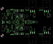
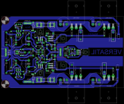
I will make some little changes on layout espacially zobel position that will alowing to reduce a little bit the board.
Marc
Let's assume the Toshiba outperform the LATfet or HEXfet.
Gabor
It already did!!
I my case defenetly, but my config is using 2 pairs of drivers - like BJT version.
I have 8 pairs of toshiba mosfets but if they arent in production anymore I will have to get few more for future development.
hi Borys,
Would advice to go with or without driver stage for one pair? In your config. have swap Bjt in bias servo by IRF540 as ever do?
Same PCB (with or without) can be use i think by omitting bjt driver transistor and change 4r7 by a jumper but that goes to collector bjjt and no to base. Also zener must be added.
Marc
Marc
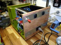
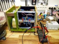
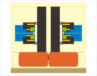
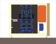
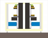
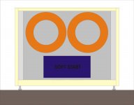
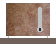
I am on Holliday in one week and will begin BG1 enclosure work. It will be made with MDF painted for "body" and veneer for front. The enclosure size is 33(L)x31(deep)x25(H) cm Under 5 project drawing :
1 - front view (maplpe veneer)
2 - front view without front plate
3 - front view without front panel+Trafo and soft start compartiment
4 - open side view
5 - top view
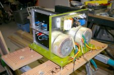
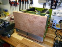
The architectur is about the same as the Nmos 200 i build (see picture) witout rectifier and caps rank in the middle replaced by capacitance multiplier direct under amp board on heatsink. Heatsink that will be used for BG1 are the same : 230x200x40mm with 10mm base
Marc
1 - front view (maplpe veneer)
2 - front view without front plate
3 - front view without front panel+Trafo and soft start compartiment
4 - open side view
5 - top view
The architectur is about the same as the Nmos 200 i build (see picture) witout rectifier and caps rank in the middle replaced by capacitance multiplier direct under amp board on heatsink. Heatsink that will be used for BG1 are the same : 230x200x40mm with 10mm base
Marc
Attachments
-
 nmos_200_7.jpg55.2 KB · Views: 266
 -
 nmos_200_6.jpg59.7 KB · Views: 271
 -
 nmos_200_1.jpg45.5 KB · Views: 233
 -
 BG1-top.jpg175.8 KB · Views: 187
 -
 BG1-side.jpg82.1 KB · Views: 176
 -
 BG1-front3.jpg54.3 KB · Views: 130
 -
 BG1-front2.jpg51.9 KB · Views: 134
 -
 BG1-front1.jpg57.5 KB · Views: 255
 -
 nmos_200_8.jpg53.1 KB · Views: 238
- Home
- Amplifiers
- Solid State
- FET-hex explendit amplifier