If I am not mistaken , at first sight , you have a positive feedback amphere...check output stage transistors configuration... Also feedback return point should be taken at output of amp and not source resistor...
Fab
Thanks Fab.
You are right.
Cheers
Dom
What do R19 /20 with their associated capacitors do here ?
Feed supply ripple to the output terminal ( with a low Zout!)?
Why two Zobel networks ?
If D1 and D2 are protection for the MOSFET gates than shouldn't they be zeners?
Thanks for the reply.
R19/R20/D1/D2/Caps are bootstrap. check post 408. Although I am concerned my 1N4002 diodes are not beefy enough.
The two Zobels; I wondered why there were two also. I copied this straight from Borys schematic.
Not sure what you mean by feed supply ripple to the output terminal. can you elaborate?
cheers
Dom
Hi folks, I have been following this thread for a while and have decided to build my own. I have created the attached schematic based on Borys earlier schematic except with partys that I have. Can you have a quick glance over it for any mistakes before I create the board etc?
Thanks
Much appreciated.
Dom
[/URL][/IMG]
If you do not need do not put bootstrap components (there is missing 50% of the boostrap circuit anyway, two types of boostrap were tested). Diodes between output and mosfets gates should be 15V zeners. Diodes separating supply schould be installed but they are not necessary. Regards

Thanks Ashok and Borys.
I have updated schematic and created PCB below.
Gost22 unfortunately I have only IRF540/9540.
I have updated schematic and created PCB below.
Gost22 unfortunately I have only IRF540/9540.
An externally hosted image should be here but it was not working when we last tested it.
An externally hosted image should be here but it was not working when we last tested it.
Thanks Ashok and Borys.
I have updated schematic and created PCB below.
Gost22 unfortunately I have only IRF540/9540.


Another small thing. I just spotted on your schematic, with IRFP version I have used IRF transistor for bias compensation - tahan bias is rock solid. With bd139 (I had board like this too) the bias was overcompensated approx 40%. Better idea is to use same type of the bias servo transistor as the output one.
Regards
Hi guys!
For output mosfets transistors I would put a couple IRFP9240/IRFP240!!
cheers!
If you go to the front of these tread you will find the schematic for the IRFP mosfet type you have.
Thanks to Borys.
Also there are some already tested and built sample sou you do not need to start from step one.
Greetings G
Domyboy, then OK!?
IRF540 ---> Id=17A; Ptot=45W
IRFP240 ---> Idmin=20A; Ptot=150W!!
cheers!
I recommend irfp240/9140 as a pair, just take a look at rdsON and rest of the parameters (input capactance etc), they look imho most similar.
I recommend irfp240/9140 as a pair, just take a look at rdsON and rest of the parameters (input capactance etc), they look imho most similar.
Hi guys!
For the record: IRPF240/IRFP9240!!
and not like this: irfp240/irfp9140??
cheers!
I recommend irfp240/9140 as a pair, just take a look at rdsON and rest of the parameters (input capactance etc), they look imho most similar.
IMHO, the Rdson does not need to be matched.
Unless you actually want to use the mosfet as a switch - and that will certainly not be the case in an amplifier.
In an amplifier the mosfet must never be full on and never full off.
So you can forget the switching times and the resistances from its parameters when comparing, imo...
Last edited:
IMHO, the Rdson does not need to be matched.
Unless you actually want to use the mosfet as a switch - and that will certainly not be the case in an amplifier.
In an amplifier the mosfet must newer be full on and newer full off.
So you can forget the switching times and the resistances from its parameters when comparing, imo...
Thanks
Pleas take a look at input capactance too, there is no need to use different resistor for N and P channel in this case. I have tested this pair at very high speeds and everything looks very symetrical !! (pair 240/9240 in amplifier at very high speeds and capactive load doesnt do the job as good as 240/9140 pair, i did not read this on internet but tested it on the bench with scope).
Last edited:
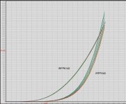
I vote for 240/9140 as a best matching pair...
Are you sure?
It`s more like the other way around..
240/9140 is a better match for audio, provided the voltage rating of the latter is kept in mind.
Attachments
And graph for 9240/240 ?
Didiet
Attachments
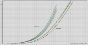
If you have a chance please check high speeds transients of the above transistor pairs. THD on pair irfp240/9140 is very good and amp behaves really good on square tests. I will test later on irfp240/9240 pair as suggested. (I remember I had some unsymetric scope measurements with those).
- Home
- Amplifiers
- Solid State
- FET-hex explendit amplifier