Rigidity is achieved when they are glued together but I do need to beef up the end plates as they aren't thick enough to hold hurricane nuts for attachment of a baseplate.
I use insert nuts for these sort tasks much better than hurricane nuts
Like these, available from many different places
Threaded Inserts For Wood | E-Z LOK
I prefer to use hurricane nuts and then hold my breath each time I loosen the bolt. 🙂
Seriously,I've had good luck since I started gluing them in.
I do have some of those inserts tucked away somewhere. I'll dig them up and use them if it looks like they would fit.
Seriously,I've had good luck since I started gluing them in.
I do have some of those inserts tucked away somewhere. I'll dig them up and use them if it looks like they would fit.

Aah great, glad it helped. I was going crazy tying to figure out clamping sometimes, until I stumbled on the tape method (out of desperation probably 🙂)
Looking forward to hearing how full rig works out...
Looking forward to hearing how full rig works out...
Concerning the line array/baseplate attachment and how to best implement it:
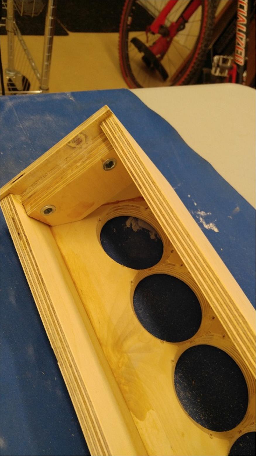
I went though a similar process in the design and realization of my Modified CBT24 project. Kevin Kendrick went with my desire to have a removable baseplate so my arrays could be moved and easily reassembled when desired. Kevin designed a U shaped metallic plate that was inserted inside the cabinet. With threaded taps the baseplate and array tower can be separated yet a strong, rigid connection is achieved. Take a look at the photos during the tower design and construction stage in this thread:
Jim's new CBT Arrays -
Techtalk Speaker Building, Audio, Video Discussion Forum
Notice how the U shape metal piece enhances the strength of the base plate/tower attachment and achieves the desire to have threaded attachment for these two components. The U piece also stablizes the tower sidewalls as well. It was glued and screwed into the cabinet.
Seven internal braces helps to make the towers (realized with half inch thick MDF) stronger. The baseplate was realized with 1 inch thick MDF.
Last edited:
Hi Jim:
I'm well aware of your thread. Its what initially steered me towards the SB65. My previous favorite had been the Fountek FR58EX, which is also a nice driver.
My cabinet volume is considerably less than yours, I believe. Simulation predicts QTC=1 and I planned on DSP so little point in making it larger. Since its so small in cross section, the only braces called for were lengthwise and the sides brace each other. The only problem I had due to the lightness is a tendency to warp before I got the plywood sealed. Still, if I had to do it over, I would use 15mm BB instead of 12.
I went looking for angle stock for the base at HD before I say how light my proto was, but ultimately I didn't bother. Being straight, instead of leaning over backwards, takes a lot of pressure off the joint at the base.
But I'll sleep better with threaded inserts in the base instead of hurricane nuts.
Here is a close up of the baffle with the tape clamped mitered joint and showing my recovered 1/16" pilot holes.
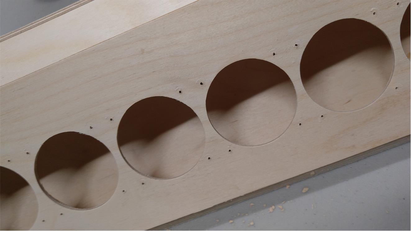
Next step: gluing the other side of the baffle to the back plate. I won't use many clamps here, I'm going to tack it down with brad nails and then maybe I won't feel like I have to let the glue dry overnight before moving on.
Next step: gluing the other side of the baffle to the back plate. I won't use many clamps here, I'm going to tack it down with brad nails and then maybe I won't feel like I have to let the glue dry overnight before moving on.
Attachments

Next step: glued and nailed and waiting for the endplates being prepped with hurricane nuts (my inserts were too large)
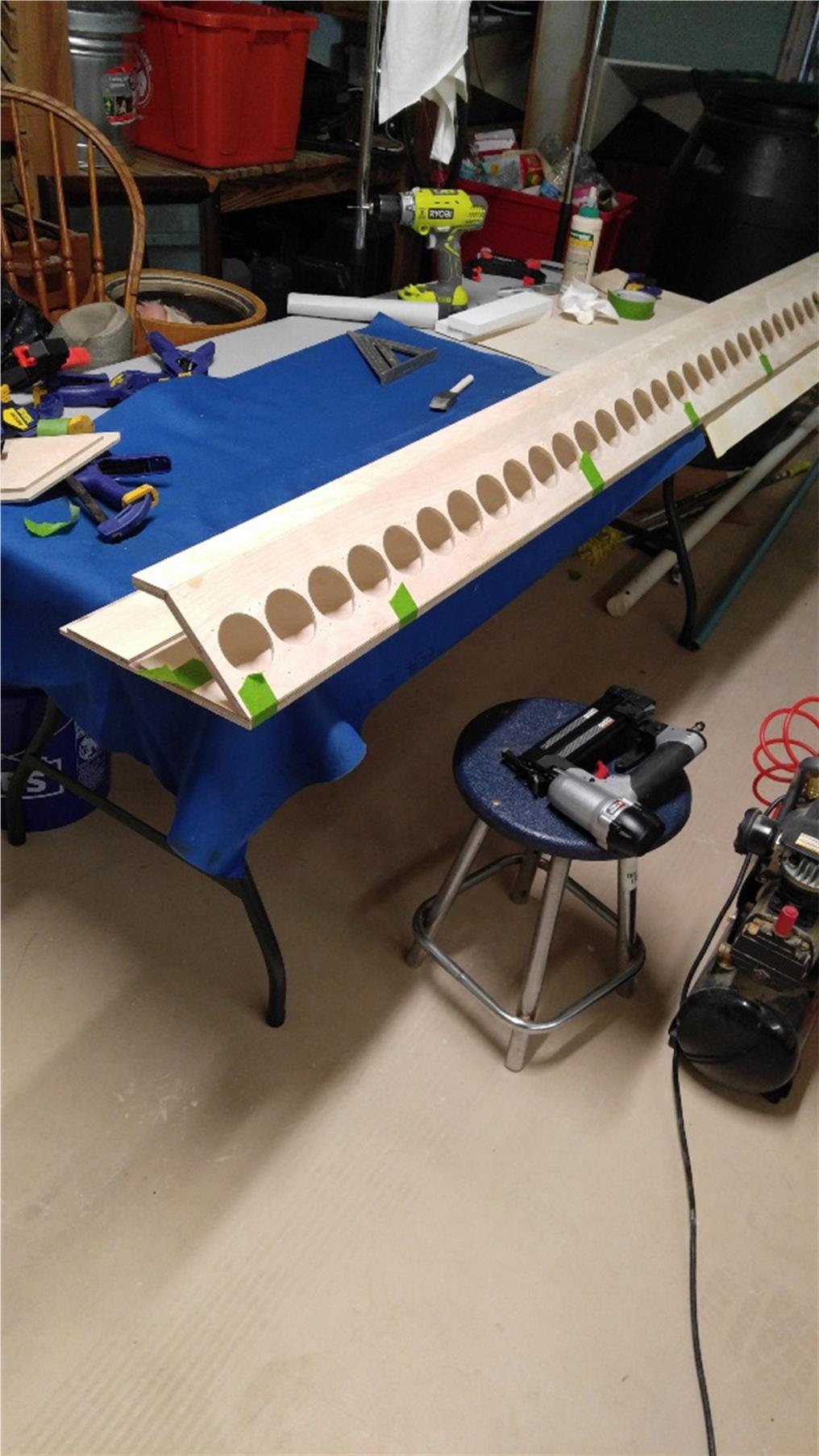
and in case you are wondering what I'll screw up next, one of my many brads poked through to the other side. just one I call a victory!
and in case you are wondering what I'll screw up next, one of my many brads poked through to the other side. just one I call a victory!
Attachments

Its ready to have the drivers mounted, except I need to paint it first. Its been two days prepping for paint as I had some filling to do and kept finding more that needed to be done.
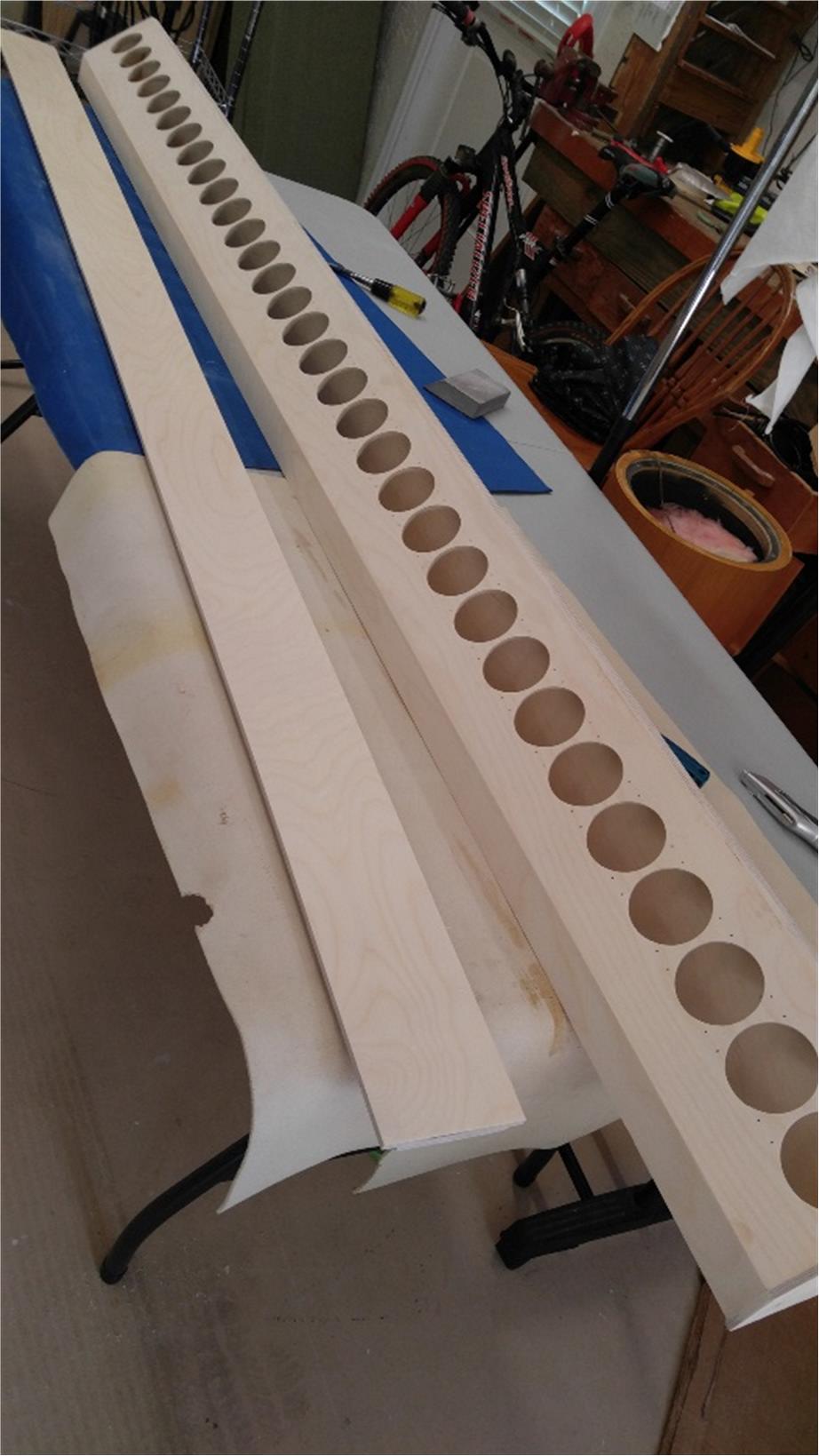
and I went for threaded inserts, literally to Home Depot, only 1.5 miles away. glad I did. it was so much easier and clearly more robust.
and I went for threaded inserts, literally to Home Depot, only 1.5 miles away. glad I did. it was so much easier and clearly more robust.
Attachments


I painted it to match the absorber panel fabric, which missed its intended match to the walls but happily turned out to be an almost perfect mate to the floor tiles.
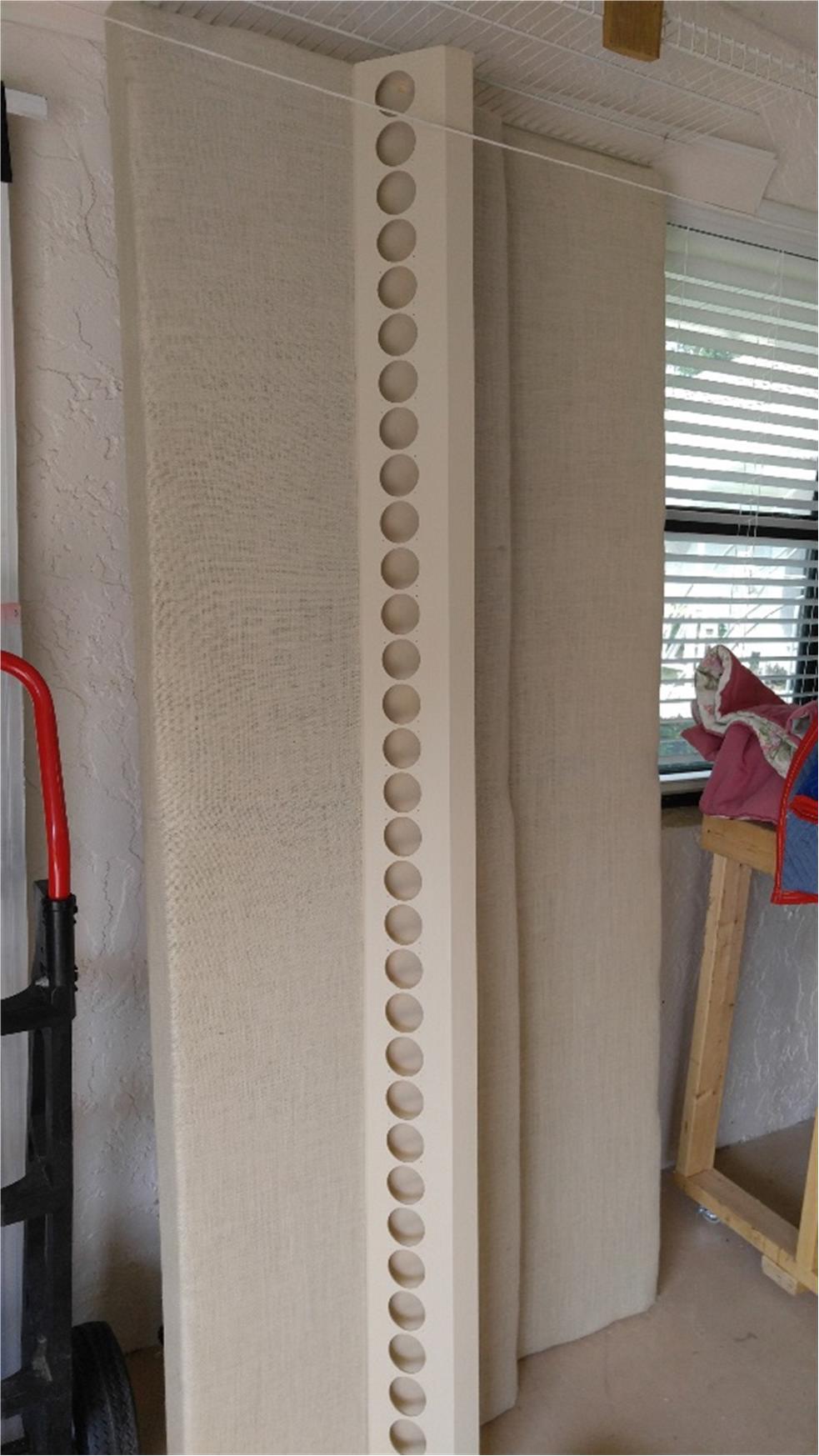
Imagine the line of black and silver driver cones...if that doesn't work I'll have to wrap the entire tower in fabric.
Imagine the line of black and silver driver cones...if that doesn't work I'll have to wrap the entire tower in fabric.
Attachments


Mounting and wiring up the drivers proceeded without incident until I ran out of the correct gauge hookup wire.
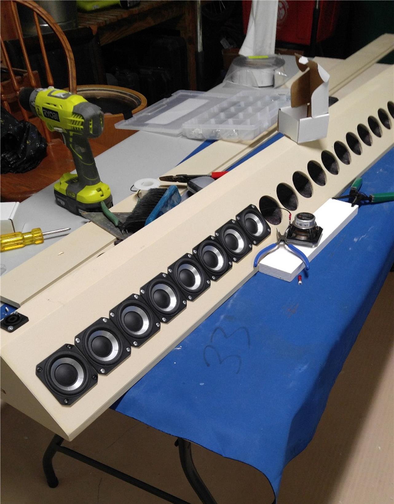
Notice I've painted the heads of the mounting screws of the first driver black. I want to get a better/smaller brush before doing the rest of them.
Notice I've painted the heads of the mounting screws of the first driver black. I want to get a better/smaller brush before doing the rest of them.
Attachments

Most of the fastener/hardware stores around my small town have little to no black screws.
So I buy black oxide wood screws from Parts Express for my projects. They have various sizes (threads and lengths). No painting needed.
Jim
So I buy black oxide wood screws from Parts Express for my projects. They have various sizes (threads and lengths). No painting needed.
Jim
darn you are right. they have black #6 pan head which would have worked.
but shipments from PE take almost a week to get here while McMaster Carr delivers overnight at no extra cost. Made me forget about PE for most of my needs
but shipments from PE take almost a week to get here while McMaster Carr delivers overnight at no extra cost. Made me forget about PE for most of my needs
progress!
Twelve drivers to go but I need a break!
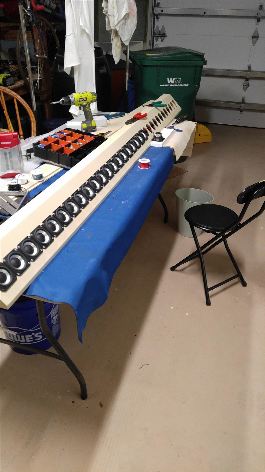
While McMaster Carr gives me overnight delivery, stuff ordered on the weekend doesn't ship until Monday arriving late Tuesday. While waiting the garage ate 200' of speaker wire as I endeavored to get all the cables to the arrays and woofers off the floor.
Twelve drivers to go but I need a break!
While McMaster Carr gives me overnight delivery, stuff ordered on the weekend doesn't ship until Monday arriving late Tuesday. While waiting the garage ate 200' of speaker wire as I endeavored to get all the cables to the arrays and woofers off the floor.
Attachments

Did you include he TC9 in your driver evaluation and how did you find them against the SB driver?
//
//
I did some FR measurements but no listening tests. I took for granted it can be made to sound nice. I intended to go with a smaller driver from the start.
wiring done
I've got all the drivers mounted and connected

but I need to dress the wires a little and stuff the cabinet with fiberglass before I button up and make music. That is 1/4" of soft felt on the wall behind the drivers.
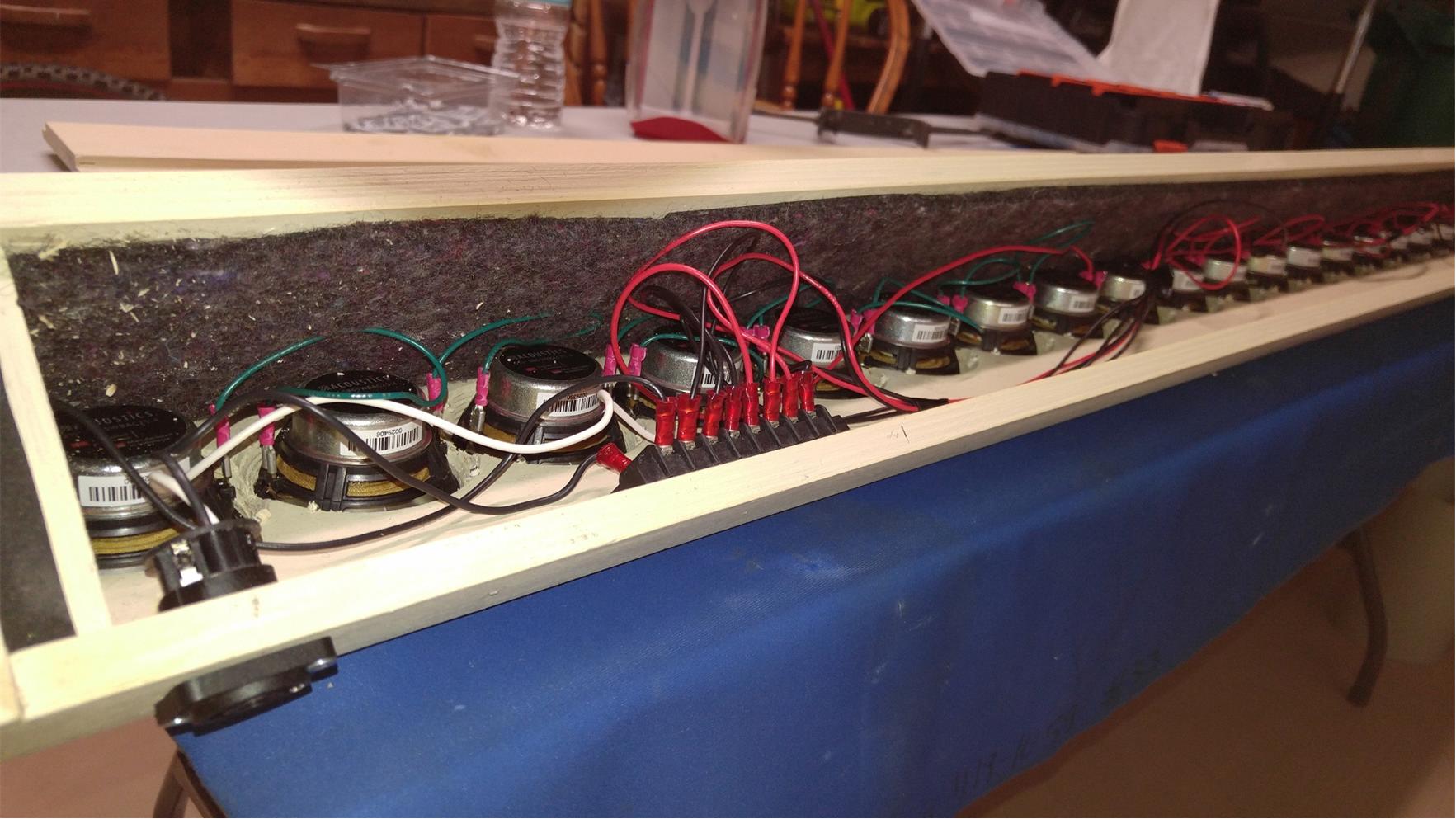
Groups of 8 drivers are wired in series with ~7" jumpers between adjacent drivers, extra long to allow me to grasp the unmounted driver's terminal with needle nose pliers while pushing the terminals on. The paralleling is done at the terminal block.
I've got all the drivers mounted and connected
but I need to dress the wires a little and stuff the cabinet with fiberglass before I button up and make music. That is 1/4" of soft felt on the wall behind the drivers.
Groups of 8 drivers are wired in series with ~7" jumpers between adjacent drivers, extra long to allow me to grasp the unmounted driver's terminal with needle nose pliers while pushing the terminals on. The paralleling is done at the terminal block.
Attachments


- Home
- Loudspeakers
- Full Range
- Full range line array for wall or corner placement