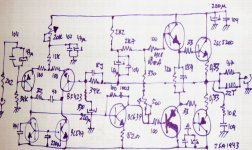
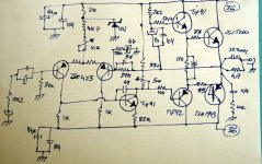
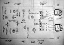
The upper bias resistor is 330 ohms... and
The drivers transistors are 2SB649A and 2SD669A.... gain is high...more than 150
The output coil used 22 turns over a 4.7 ohms resistor
Zobel is the standard...100N and 10 ohms
I am sure that you will scream loud because of happyness if you construct this amplifier....Dx amplifier....the Aksa cousin...or Aksa co-incidence
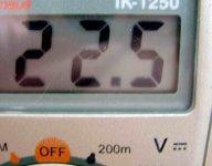
The image attached is showing measurement during bass peaks...supply voltage was 36 plus 36Volts...and filter bigger than 10000uf each rail...this may be 120 watts RMS...hummm..good!
regards,
Carlos
The drivers transistors are 2SB649A and 2SD669A.... gain is high...more than 150
The output coil used 22 turns over a 4.7 ohms resistor
Zobel is the standard...100N and 10 ohms
I am sure that you will scream loud because of happyness if you construct this amplifier....Dx amplifier....the Aksa cousin...or Aksa co-incidence
The image attached is showing measurement during bass peaks...supply voltage was 36 plus 36Volts...and filter bigger than 10000uf each rail...this may be 120 watts RMS...hummm..good!
regards,
Carlos
Attachments
I remember that 2 years ago i tried to modify Aksa, as i was not happy with the bass
And tweaking into original Aksa board i could produce better bass...and worst treble.
This repeated once again...not the amplifier is not an Aksa...current and values very different..only thopologie is the same as the Old Aksa (not the new Lifeforce that is very different)...this time amplifier was calculated since the first resistor...and result was sligthly better in power related what i have made 2 years ago...having Aksa boards and producing modifications over it.
No one could match Aksa trebles..... i couldn't too.
Congratulations to me...i have made mine...and congratulations to Mr. Hugh Dean, as he designed a real champion.
Aksa secrets not shown in the schematic....not used in my circuit too.
regards,
Carlos
Attachments
A three day wonder !!!
Of course you took a lot of time in the design phase, but still, from doodles to an operating amp in less than three days is quite a feet >>> congratulations to You indeed.
(How does it sound? ... after you have finished with the tweeks, tuning, etc.)

Of course you took a lot of time in the design phase, but still, from doodles to an operating amp in less than three days is quite a feet >>> congratulations to You indeed.
(How does it sound? ... after you have finished with the tweeks, tuning, etc.)
Those modifications made the amplifier better during turning on.
Power on "thump" is almost silent...but the amplifier lost "that" live..that audio quality.
I removed rail filters and rail resistors, as i will use stabilised power supply.... was simplified.
This one sounds very normal...nothing special i think...the other one...the crazy one with enormous speaker excursions during power on had clearly better sound.
I am not satisfied with both of them.... as the silent unit without thump sounded sterile.... the beautifull sound unit may burn your speakers (or mine!).
I think i have to study more, research more, observe more and improve this schematic a little bit more.
Thank you by the attention guys,.
Here the silent sterile amplifier....hummmm...the first one sounded very good...a respectable lovely amplifier...but this one...grumpf!
THis one is a "crab"...hehe
regards,
Carlos
Attachments
here is an interesting chip amp circuit: http://www.diyaudio.com/forums/showthread.php?s=&postid=1119669#post1119669 ... might be able to pull a few tricks off of this ... like snubbing caps on each power rail set ... using 10,000 to 1 ratio, electro to plastic (uF to nF) ... 
I have made modifications, model 3 is now sounding.
It is a variation related the first one.
This one has no noise during power on and power off.
This one sounds good in treble and bass.
This one lost power because i have used bad voltage amplifier transistor..this TIP41 used had 90 of gain only...when normally i use 150 of gain there.
Also drivers used are TIP41 and TIP42...those ones are cheap and normally good...but frequency response of those ones do not reach radio frequency...this result in a more stable amplifier (I think)
Those things i show you are really constructed and they were tested real life..so..if you wanna construct go ahead..because tested and guarantee that will sound...and that you will be able to adjust off set and bias without any problem.
This third one is cheap and simple....with good sonics....power had losses because transistors used.
regards,
Carlos
Attachments
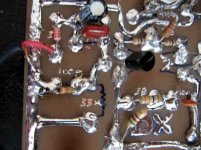
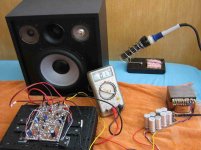
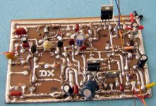
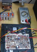
This is not a simulated result...this is real life testing
Simulators can work fine or explode in front of your nose...and normally you have to work hard to debug them.
This is plug and play.... no problems!
The image is here to show you that it was really constructed.
regards,
Carlos
Simulators can work fine or explode in front of your nose...and normally you have to work hard to debug them.
This is plug and play.... no problems!
The image is here to show you that it was really constructed.
regards,
Carlos
Attachments
Satisfation!!!..this one satisfies me 100 percent...sonics wonderfull!
As many friends knows...i don't give a sheet ... (of paper)..filled with specification to you guys....because i do not bother with numbers.
I want special sonics.... emotion.... paradise...dreams...not numbers.
If distort or not...if has intermodulation (IMD) or not...i do not mind...i will continue to be happy and listening this special amplifier...this is MINE!
I hope someone enjoy it too....it is hard to be happy alone.
Well..at least my near friends will try..for sure.
I think that there's no schematic that cannot be improved...i forgot rail condensers in this one...also better transistors will reproduce better sound too.
Off set is around 3 milivolts...stand by current is 85 miliamps.
regards,
Carlos
Attachments
To complete the information, as forum is an ethernal memory for all of us
...To pre-adjust the bias trimpot (500 ohms or 100 ohms) adjust it to read 80 ohms at the ohm meter.
Also adjust the off set trimpot (10K) to a resistance around 7K2
Off set can be adjusted to around 3 milivolts
Bias will be "the one will provide more than 550 milivolts in every output transistors"...in my own case was 80 miliamps.
The drivers transistors do not need a heatsink.
If you will use small heatsink, substitute the 330 ohms plus 500 ohms variable potenciometer by a 3 diodes 1N4001, in series with a 100 ohms resistance in series with the diodes...install diodes touching the heatsink...do not forget to insulate the diodes leads to avoid short circuit...some heat compound...silicon grease may help the heat transfer to the diodes.
I prefer to use enormous heatsink and a fan blower..but others prefere some "automatic control" over stand by bias.
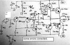
The first transistor VBE is 630 milivolts...input shorted..output connected, 35 volts supply...plus and minus.
The second one, the feedback transistor measured 627 milivolts
The Voltage amplifier measured 581 milivolts, a NPN one, 2SD669A...with 150 of gain
The upper driver, a NPN one, measured 568 milivolts (BD139)...with 115 of gain
The lower driver, a PNP one, measured 551 milivolts (BD140)... with 125 of gain
The upper power transistor, a NPN one, measured 601 milivolts..this one a fairchild 2SC5200... 105 of gain
The lower power transistor, a PNP one, measured 603 milivolts...this one a fairchild 2SA1943...95 of gain
I hope this can help someone to construct...well...this is an invitation to you.... happyness guaranteed!
regards,
Carlos
...To pre-adjust the bias trimpot (500 ohms or 100 ohms) adjust it to read 80 ohms at the ohm meter.
Also adjust the off set trimpot (10K) to a resistance around 7K2
Off set can be adjusted to around 3 milivolts
Bias will be "the one will provide more than 550 milivolts in every output transistors"...in my own case was 80 miliamps.
The drivers transistors do not need a heatsink.
If you will use small heatsink, substitute the 330 ohms plus 500 ohms variable potenciometer by a 3 diodes 1N4001, in series with a 100 ohms resistance in series with the diodes...install diodes touching the heatsink...do not forget to insulate the diodes leads to avoid short circuit...some heat compound...silicon grease may help the heat transfer to the diodes.
I prefer to use enormous heatsink and a fan blower..but others prefere some "automatic control" over stand by bias.
The first transistor VBE is 630 milivolts...input shorted..output connected, 35 volts supply...plus and minus.
The second one, the feedback transistor measured 627 milivolts
The Voltage amplifier measured 581 milivolts, a NPN one, 2SD669A...with 150 of gain
The upper driver, a NPN one, measured 568 milivolts (BD139)...with 115 of gain
The lower driver, a PNP one, measured 551 milivolts (BD140)... with 125 of gain
The upper power transistor, a NPN one, measured 601 milivolts..this one a fairchild 2SC5200... 105 of gain
The lower power transistor, a PNP one, measured 603 milivolts...this one a fairchild 2SA1943...95 of gain
I hope this can help someone to construct...well...this is an invitation to you.... happyness guaranteed!
regards,
Carlos
Attachments
Use a good supply, with low voltage variation when you load it to 5 amps.
Use condensers with more than 10000 per rail...but do not go up than 30000uf please!
Include slow speed fuses of 5 amperes each rail and also in the output.
The 2SC5200 and its complementary is holding full volume distorted for many minutes.... the heatsink temperature controled around 45 degrees.... with clipping.
The amplifier do not goes over 20 volts....and this is already a clipping output.
Install a fuse in the output too.
Use short lengthes of cable from supply to the amplifier...but it is better to include, at least, 470uf directly over/under/near the board....i use to bypass with 104...but this is your personal choice.
And he bappy..for sure you will be.
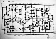
Here is some idea to your board...but in reality, people loves to do by themselves..i think this is great..but to complete informations, here is a suggestion.
regards,
Carlos
Use condensers with more than 10000 per rail...but do not go up than 30000uf please!
Include slow speed fuses of 5 amperes each rail and also in the output.
The 2SC5200 and its complementary is holding full volume distorted for many minutes.... the heatsink temperature controled around 45 degrees.... with clipping.
The amplifier do not goes over 20 volts....and this is already a clipping output.
Install a fuse in the output too.
Use short lengthes of cable from supply to the amplifier...but it is better to include, at least, 470uf directly over/under/near the board....i use to bypass with 104...but this is your personal choice.
And he bappy..for sure you will be.
Here is some idea to your board...but in reality, people loves to do by themselves..i think this is great..but to complete informations, here is a suggestion.
regards,
Carlos
Attachments
Local friends were invited to come to listen to the amplifier...my Club members may..
come soon.... they will give me a feedback...as we always love whatever we do...so....other guy's evaluation is a need.
Also some internet friends may construct too.
If aproved...the DX International will be a target.
This one is the fouth schematic done...i feel this one excelent...so..i will stop reseaches in this one.
hehe
Carlos
Attachments
Thank you Sheldon....it is sounding great..for sure it is.
Guaranteed of quality..sounding good.
The emitter resistors are a very good protection..but, as Jan Dupont used to say..everything you install between the amplifier output and the speaker will destroy the bass..in special resistances that may create problems related damping.
Was clear the sonic difference without the resistance...the bass punch was clear bigger.
Of course, having more than one transistor to each rail, you will need to use those resistors to equalize current because the gain differences between them.
Using only one transistor..you can avoid that resistor.....i am thinking to test the output inductor supression too.
How that resistor works, as you may know Sheldon..when current increases, a bigger voltage will be over this resistor...reducing power to be held between colector and emitter..also it will limit maximum current...hehe..in this case...more than hundred amperes...hehe...not good enougth.
Those resistors are inductive..or..at least i can find only inductive ones here...the non inductive i found are giant ones...not good to use them.
You can test with and without....i think the amplifier is near its limits using 4 ohms.... and i am using exactly 4 ohms to test it.... a resistor there may be good to the circuit...but it is really bad to sonics.
regards,
Carlos
My dear friend Sunrise....happy i am to find you here.
Thanks by you attention Mister.
You know that everybody loves Sunrise.
For sure i love you my dear friend....we have more than 2 long years using direct E mails...very pleasant they are to me..we use talking audio mails..using MP3 recordings folks.
Sunrise.... guys....he is one of the partners of a very nice company that construct DAC ....the Pulse Company, stablished in East European States.
regards,
Carlos
Attachments
- Status
- This old topic is closed. If you want to reopen this topic, contact a moderator using the "Report Post" button.
- Home
- Amplifiers
- Solid State
- Full throttle construction of amplifiers