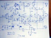
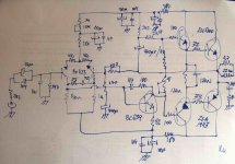
The schematic i will try in advance will be this one
The rule is absolute supply stability.... no supply wavings...no supply modulating stages.
No VBE multiplier...good heatsink instead of it.
Voltage amplifier mirrored.
Aksa transistors in the output....the ones Hugh use...2SC5200 and 2SA1943...also drivers the same Hugh is using...because they are cheap and reliable.
Diferential with some stabilized voltage in the long tail..maybe some CCS in the future.
Eva stile capacitors and resistor in series substituting Miller capacitor at the VAS and avoiding possible oscilations in the input differential.
I will try not to have hot transistors...so..resistors may be changed.
Well.... everything there..included the supply... are things that i have apreciated in many amplifers...now...i will join those things together to see if they will work fine joined.
regards,
Carlos
Attachments
You may have imagined a very complicated schematic.
Hummmm...complicated schematic normally do not sounds good.
I have constructed more than 3.6K amplifiers...and i can say that.
The most simple the better the sonics..with exceptions...alike Symassym and some others...including Lifeforce....beautifull sonics from Lifeforce.
regards,
Carlos
Hummmm...complicated schematic normally do not sounds good.
I have constructed more than 3.6K amplifiers...and i can say that.
The most simple the better the sonics..with exceptions...alike Symassym and some others...including Lifeforce....beautifull sonics from Lifeforce.
regards,
Carlos
Attachments
... those "strawberries" are actually heirloom baby cherry tomatoes, home grown.
The use of Zeniers to "set" a voltage reference is more than most would bother with = and does produce a more repeatable, reliable, cooler running PS. You obviously know a great deal about power conversion.
I also notice that you "snub" every large electrolitic cap with a plastic cap ... what "rule of thumb" do you use to determine snubbing size vis a vis electro cap size? 1uF to 5uF? 1 to 20? 1 to 100? Do snubbing caps produce faster response from power storage = reduced amp output "fatigue"? ... and faster startup?
... and what general rules do you have about voltage limits on caps? (63 volt caps on 30 VDC rails? or something tighter?)
3600 amps! Well, there is your model number = Type 3601 ... ... After 3K amps, it is about time you took the plunge w/ your own design.
+/- 30 VDC would indicate a potential of around 100 watts ... no?

The use of Zeniers to "set" a voltage reference is more than most would bother with = and does produce a more repeatable, reliable, cooler running PS. You obviously know a great deal about power conversion.
I also notice that you "snub" every large electrolitic cap with a plastic cap ... what "rule of thumb" do you use to determine snubbing size vis a vis electro cap size? 1uF to 5uF? 1 to 20? 1 to 100? Do snubbing caps produce faster response from power storage = reduced amp output "fatigue"? ... and faster startup?
... and what general rules do you have about voltage limits on caps? (63 volt caps on 30 VDC rails? or something tighter?)
3600 amps! Well, there is your model number = Type 3601 ...
... After 3K amps, it is about time you took the plunge w/ your own design.+/- 30 VDC would indicate a potential of around 100 watts ... no?
Oh...Tomatos....good ones too....hummm..with cheese!
The capacitors are there only to represent a low impedance patch to ground...because electrolitic condensers are highly inductive...so..if some oscilation start...the capacitor will "eat it"...and beeing big (100N) it will be a short to those frequencies.
Well...snubbers...well,..i never could perceive any sonic difference using snubbers...maybe because i do not know how to calculate them...but using other guys calculation i did not perceive nothing going there....but for sure will avoid oscilations too....you can call my capacitors some snib...as it is not snub.
The good rule is to use twice the voltage....the supply peak to peak and a little bit more for safety...well..i use the ones i have within its voltage limits...adjusted to the stand by voltage over it...but for AC points...you must use twice or more referenced by the stand by voltage...good is to use the supply peak to peak voltage as reference.
Hey!...do not ask me those theoric things.... i do not know those things...i have in memory that people use 22 uF when current is low...47 when current is around 10 miliamps and 100 or 220uf when current is higher.
hehe...my amplifier will explode...if my amplifier, it, personally bother itself too much related theory it will explode...for sure.
regards,
Carlos
Model 3601 is a nice idea FastEddy...but i am not sure of those numbers
Was something calculated because i have not paper registrations of all i made.
I just remember that i used to construct daily... and that i used to repeat the same amplifier 2 or 3 times because errors of construction... burns of parts and improvements in the board.
The boards were made with wood with copper nails... those points were joined with telephone wires...hehe...good old days.
I started to register amplifier a couple of years ago when i started in this forum...more than 300 was constructed...giving a ration of one amplifier each 2 days.
But in early days...when i was very young...the ration was better than that.
Around 17000 days from 1960 to our days.... around 20 percent of those days i had used 3 to 4 hours to construct things..from magazines....more than 70 percent explode in my face...others sound terrible.... a big majority had magazine publishing errors...some sounded nice.
They were dismounted and parts used to other amplifiers....and i do the same now a days...as i would need an Airplane Hangar.... or a football place to stock all those amplifiers.
Dreaming with the paradise....never found.... and giving extreme value to Sansui, Pioneer, Marantz and Kenwood...as they used to produce better sound than i could make those days.
And i continue with that behavior...construct things to listen only...i just cannot give up related that.... but i will try to concentrate efforts to produce my one...it is time to do that.
Yesterday i was searching for resistor...resistance...my God!..i could not believe that tinny thing would dissipate 1/2 watt...and was expensive....6 for a dollar!..... i visited friends that have repair shops and i fill my car with junk to be cleaned, dismounted, measured and selected....there my resistors..veterans...tested, reliable and BIG!
regards,
Carlos
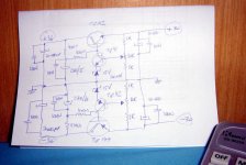
Board is going to the "revision department"... the next door
Using another pen and using new glasses.
I will paint the parts over the board...they will be soldered over the board...when the work was done...alcohol will remove the permanent pen ink (not permanent)
Those parts values, painted, will be the guide to solder the real parts over the cooper....after finished...paint will be removed as will not serve anymore.
regards,
Carlos
Attachments
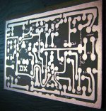
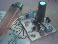
Tomorrow it will be sounding if not too much bugs to find.
Here is the board...parts will be soldered over the copper...at the copper side...no holes will be made...board will be glued over the heatsink.
That paint was made to check, to find errors and to be my guide when installing parts.
After that...board will be washed using Kerozene, Alcohol and watter and soap (that one hard..used to clean dogs...the one that can clean even bad thougths)
regards,
Carlos
Attachments
That's rigth fastEddy.... because of that i made this name choice.
Nordic....if i understood you need a 2,2 picofarads capacitor...this can be constructed using 2 pieces measuring 15 milimeters each one twisted.....hehe...of course insulated wires, twisted tigth, 5 helical turns..... some VHF radio can be captured using that small capacitance.... with the normal small inductances from the circuit you may pick an FM Broadcasting station.
Of course depends the place this capacitor is installed.
Nice that.....Graham is good using Radio Frequency.... i think the place will not oscilate.
regards,
Carlos
" ... you need a 2,2 picofarads capacitor... this can be constructed using 2 pieces measuring 15 milimeters each one twisted.....hehe...of course insulated wires, twisted tigth, 5 helical turns ..."
Ohhh watch out for that stray capacitance and the inclusion of the inductance component ... FYI: a couple of pico Farads is about right for a ham sandwitch (ham between two pieces of bread = pecular di-electric constant = low voltage only << 28 VDC) ...
Ohhh watch out for that stray capacitance and the inclusion of the inductance component ... FYI: a couple of pico Farads is about right for a ham sandwitch (ham between two pieces of bread = pecular di-electric constant = low voltage only << 28 VDC) ...
There was a digital capacitance meter as a DIY project in Popular Electronics Magazine of decades ago ... I built it and did the same = measuring everything available including cat hair & various oriental rugs = Way too much fun =
(Did you make the cap meter circuit your self? Could this be a nifty DIYAudio project?)
(Did you make the cap meter circuit your self? Could this be a nifty DIYAudio project?)
I have constructed some Radio Frequency Transceivers before the cel phone era
and i have learned those tricks during practice work.
I will not be happy to see capacimeters around...as there are people that worries too much related the small capacitance we have from copper line related the other...also people worries too much related inductances.
All those things are very small to disturb audio frequencies....those capacitances and inductances are tuning the amplifier to more than 100 Megahertz...and i hope, our friends are using lower frequency transistors...because if they start to use Radio Frequency transistors in place of the audio ones...hehe...for sure they will have transmitters and also radio frequency receivers.
When i used to operate 29 Megahertz with 100 watts, i was called many times by neighboors with complains because their amplifiers receiving my SSB transmissions.... a couple of times i have found RF transistors in the first stages of their audio appliances..exactly the most sensitive stages...and those days they used diodes to automatically limit the Vbe not to grown over 630 milivolts....that combination...diode detecting Radio frequency and High speed transistors were the problem.
Those transistors, called High Speed ones are a problem..and there are people using them now a days...and this is worst than board inductances and capacitances...but that high speed transistor use turn acceptable, as many guys are using....and the inductances and capacitances are the "big bad wolf"
I made substitution to 100 Kilohertz transistors and diode removed and all problem finished.
regards,
Carlos
hehe...he may be using some protection against oscilation
Some capacitor to ground or inverting phase arrangement to cancell oscilation.
But if not...well...there's a possibility to pick up nearby radio stations.
I do not know Pedja Rodic amplifier...normally i give up when watching fets amplifiers..the are hard to find here..so... i jump over those threads.
This is a "guarantee" that i will not visit the thead...a single Fet inclusion into a circuit and i immediatelly jump out.
When i visit down town electronic shops, and i ask them:
- Hey!..do you have Fets?
The guy answer after a big "what?"... shop guy ask me to ask the same question again...and even doing this...
- No!, conFETES only during carnival..we have not those things here.
Confetes is a small peace of rouded papper....8 milimeters diameter, many colours...used to Carnival parties..to produce a rain of colours..some tradition here...but real Fets are not a tradition here.
regards,
Carlos
Attachments

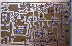
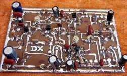
The amplifier is already built....now is time to search for bug
and to see if it will work fist time or will ask for some work.
I noticed that at least one resistor is missing in the differential...already soldered in place.
Well, it is time to observe and measure resistances searching for shorts, missing parts or other errors.
Yes...i think that this board result awfull...well...i will make better one next time...first, let's see if this unit will work fine.
regards,
Carlos
Attachments
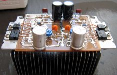
Yeah...after some tweaks it worked...aaagh...not a good sound
And them i started to go measuring and removing those extra, regulators...the CCS i have tried.... the voltage amplifier mirror that did not work fine...and them i decide to make the old and good bootstrap.
Sounded lovely..... enormous bass power...more than 22 volts over 4 ohms without big distortion (starting clipping i think).
PROBLEM...the turn on is dangerous..the wooffer movement may burn your woofer..if you construct, use some delay or insert your speaker after switch the amplifier on...even this way you have some motion.
Reality.... i had already realized that if you take some schematic, and then you go changing parts till the tone sound great!...when finished..you will have something that will remember Aksa.
This one remembers in something.....but all Hugh secrets are not included in the schematic...and it is sounding fine without those improvements.... i think sounded better related bass and had much more power than the real Aksa.....but lost the AKSONICS...that astounding quality that only Aksa can provide
Well...the better one is already designed...the best i can do is to make something around that better one.
Well...this is mine...calculated since the first component..based in good schematics i had watched during my lifetime.
Every similarity you will find with Aksa is a matter of a delicous coincidence...matter of accident, as i had not intention to finish doing an Aksa cousin.
God save the King...Mr Hugh Dean from Aspen Amplifiers...he spent 15 years and made the best one..... i have spend 45 and i could only be near Aksa quality.
No...negative..this is not a paid publicity...also not a free publicity... an accident...i have found exactly this thopologie that Hugh use....also P3A have something alike too.
I hope someone will construct... sonic quality is guaranteed.
regards,
Carlos
Attachments
- Status
- This old topic is closed. If you want to reopen this topic, contact a moderator using the "Report Post" button.
- Home
- Amplifiers
- Solid State
- Full throttle construction of amplifiers