Now start to give a good sound.
Try to reverse the HF driver. Measure the combined response with a small window. < 80msec.
In this situation and with reversed +/- of the HF driver.
You will see a dip at 1 kHz. When there is no dip the measuring window is to big and you see nothing.
Last edited:
Yellow out-phase
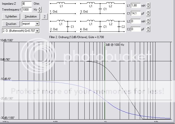
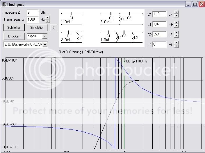
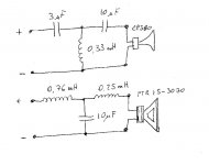
To understand the result I simulated your filter.
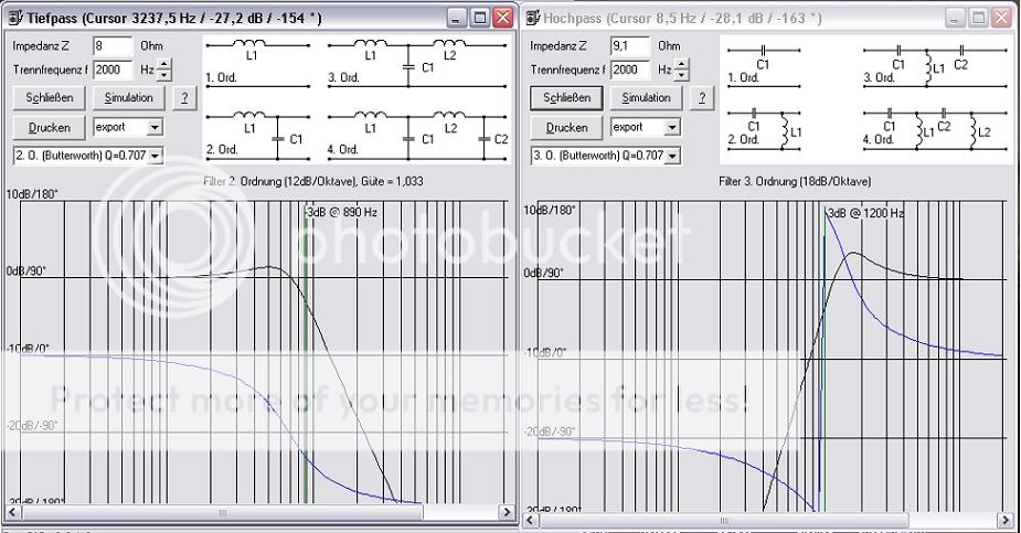
Here you see the driver do not have the same XO. So there is no opposite phase.
The HF driver is very steep cut of below 1 Khz this solves the problems there. The same with the woofer extra steep below 850Hz this solves phase problems above 1 kHz.
The dip at 900Hz is not caused by the filter I conclude must have a explanation in reflections.
Last edited:
Are you speaking about two different crossover frequency 81200Hz and low 890zHz but to see these should be simulated on real driver impedance, not costante resistance.
I simulate with the impedance of the load. I do not understand your question.
The impedance of the total speakersystem doesn't matter to much it shout not become to low and blow your amplifier.
In your situation there is a overshoot before cut off frequency that can be necessary some times, when I see the measurement of the response the rise of the SPL I can see in the graphic.
A Q of 0,707 is normal you can have easy make a LC filter with a Q of 1,2 overshoot.
Last edited:
apelizzo,
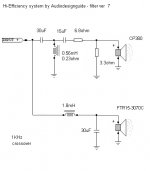
You are using DDS spherical waveguide instead of the my Stereo-Lab horn with a very flat frequency response (see plot) so we cannot use the same filter.
My idea was to use the compression band in the most wide frequency range like the hi-end japan design.
The target for these designs should be use a 2" horn to start from 500Hz but the cost are more high.
Using 1" at 1KHz there is no problem of max power because this system will be driven by single ended amplifiers with 5-20w.
We are not designing a system for PA.
Here the new 1.2KHz filter.
Audiodesign,
I like your idea to extend the horn down to 1KHz but I don't know if 1" driver can sound well so low. I think the distortion will go up. I can see ripples going up.
Anyhow to be fair, can you tell me your Mic position during your measurement. I want to do exactly as you do so I have to understand if my setup can be improved by applying your method.
I choose the DDS because I saw how the dispesion is very linear to 90 degrees. There was no chart about the Stereo-lab so I did not choose it.
Also I don't listen on axis so I don't choose directional horns.
How is the Stereo-Lab at 30 and degrees?
Last edited:
Audiodesign,
I like your idea to extend the horn down to 1KHz but I don't know if 1" driver can sound well so low.
I use a 1" driver down to 700-800 Hz in home use with no trouble. In pro one would never do this because the mixing board gorillas will blow them out every time.
I use a 1" driver down to 700-800 Hz in home use with no trouble. In pro one would never do this because the mixing board gorillas will blow them out every time.
So distortion for a 1" driver is no higher at 700-800hz than it is at say 1200hz?
So distortion for a 1" driver is no higher at 700-800hz than it is at say 1200hz?
Studies have shown that distortion in a compression driver is not perceivable, so the difference is not relavent.
Studies have shown that distortion in a compression driver is not perceivable, so the difference is not relavent.
So it is not perceivable, ok. But in my question above, the distortion is higher, right?
So it is not perceivable, ok. But in my question above, the distortion is higher, right?
I don't worry about the inperceptable, insignificant or the irrelavent, so I guess that I don't know the answer.
Audiodesign,
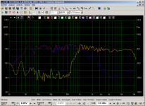
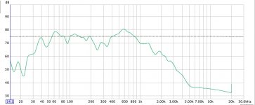
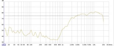
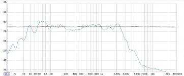
I measured the 1k crossover you proposed.
The top has changed a lot.
Similar to your measurement 16K is ~4-5dB down respect 1-2K
Forgive the non linearity of bass as the speaker was too close to the wall.
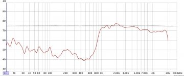
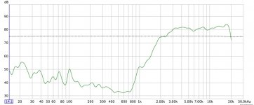
First chart my previous 3 pole crossover at 2.5K (speaker 1.5m from wall)
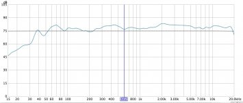
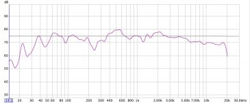
Second 1k lowpass
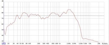
Third 1k high pass
fourth 1K full
I measured the 1k crossover you proposed.
The top has changed a lot.
Similar to your measurement 16K is ~4-5dB down respect 1-2K
Forgive the non linearity of bass as the speaker was too close to the wall.
First chart my previous 3 pole crossover at 2.5K (speaker 1.5m from wall)
Second 1k lowpass
Third 1k high pass
fourth 1K full
Attachments
Last edited:
3pole 2.5K measurement.
Sorry again for the irregularity of the bass. I left the speaker too close to the wall.
from left:
I can see the rise around 2k woofer on axis
Horn on axis
Horn 30deg off axis
Woofer on axis
Woofer 30deg off axis
Sorry again for the irregularity of the bass. I left the speaker too close to the wall.
from left:
I can see the rise around 2k woofer on axis
Horn on axis
Horn 30deg off axis
Woofer on axis
Woofer 30deg off axis
Attachments
Audiodesign,
With all respect to what are doing and the rules, for one moment forget paper, calculator and charts.
Please try my filter. PLEASE
I've done many experiments and I would like to contribute.
It's not perfect but you never know... it could be another path to your goal. You will be surprised what the CP380 can do.
I got one speaker with yours and one with mine. There is a big difference. You tell me which one you prefer.
Attachments
Last edited:
apelizzo,
I respect your design but my idea is to use the larger band for the compression driver and limit the 15" woofer to 900-1KHz.
I think your hole at 300Hz with 1.8mH and 22uF depend by the environment like the walls and by the distance of woofer from the floor.
Yesterday evening I have tested this new version and the sound is very good, the female voice is more real than the sound of my previous Monitor 2 with Audiotechnology drivers and the distortion is not present also at high level.
Now I will complete both channels with this filter and after will invite some my friends to check the result.
It is possible I will change some parts in the next days but the base for me is this (1Khz).
My mic is at 2m from the loudspeakers and an height about 90cm.
Attachments

- Home
- Loudspeakers
- Multi-Way
- Hi-End and Hi-Efficency loudspeakers (horn + onken)