apelizzo
I will do new measurements today using different times.
Good this is important because we are able to hear this first wave front. So you have to measure the first wave front.
The first wave front is theorie is called the HAAS effect. Haas effect - Wikipedia, the free encyclopedia
Regards Helmuth
The only important result is a stereo measurement on the listening position.
Here You wil see a side effect of stereo reproduction. Called comb-filter effect.
Deu the crossing of the stereo soundwaves the spl level becomes a comd ripple over it. Even if you have perfect flat responding mono speakers.

german
Kammfilter ? Wikipedia
stereo topic
Stereophonic sound - Wikipedia, the free encyclopedia
Here You wil see a side effect of stereo reproduction. Called comb-filter effect.
Deu the crossing of the stereo soundwaves the spl level becomes a comd ripple over it. Even if you have perfect flat responding mono speakers.
german
Kammfilter ? Wikipedia
stereo topic
Stereophonic sound - Wikipedia, the free encyclopedia
Last edited:
Here the compare with 341ms and 85ms.
I cannot set less than 5ms on Clio system.
My crossover point nowis about 1.5KHz.
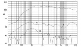
The performance of your horn is really smooth. My own measures on axes on about 70-100cm almost perfect flat.
With increasing distance it becomes a different story.
The same with measuring the low frequency to measure that. you have to take the speaker open field. I wanted to measure my previous project placed on a trapladder to create space to the ground and in the garden. To get a more relaible response.
In your graphic the comb-effect on the low frequencies caused by reflections shout be more smooth in free air. Or measure with the smallest window to measure the low frequency as I stated 42msec.
In my situation the sub-horn needs the corner to function properly so I have not much problems measuring the unit in the livingroom
Last edited:
apelizzo
your crossover frequecy since to be a little bit too high could you chek it with the plot of both driver separated ?
Audiodesign,
I will do new measurements today using different times.
I will do new separate measurements tomorrow.
Your crossover point is set at 1.5K. Is it a good practise to avoid crossover points within the voice range 1kHz to 2KHz?
That is one of the reason why I selected 2.4KHz crossover point.
I tried at 1KHz initial idea but the horn shouts horrible.
I find 2.4KHz a point where I'm just over a horn peak while the woofer is still quite smooth. So I obtain that warm and big sound stage.
This is the good part of the Celestion woofer to have that good linearity.
I will try your crossover and plot some measurements.
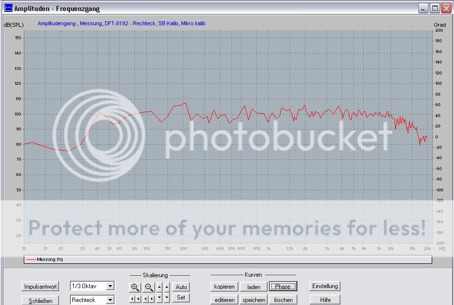
Old full range measurements
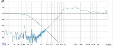
These are old full range measurements done for individual driver mounted in box. Microphone 5mm from dust cap and 5mm from driver steel mesh (horn throat).
The lower frequency excludes the reflex ports bass reinforcement.
The woofer is very linear and smooth up to 2.5KHz in this Reflex box. Why not use it? It sounds really "big". Also I feel safe to give the voice role to the linearity of the woofer at 1-2K, which is more linear here than the horn.
Other woofer at 1K are horrible but the Celestion is fantastic. The horn at 1K to 2K is not really pleasant to my ear.
On the other hand the horn had some peaks that I wanted to cut off and push the 3K energy to the upper part.
Any comment please?
I will publish new ones ASAP.
The last chart (right) is from Beyma datasheet
Attachments
Last edited:
apelizzo,
The inital idea was to keep the crossover point the lowest possible to avoid the direction problems of this large woofer.
A 2.5KHz point is good for a max 20cm diameter woofer.
Could you make all measurement with 10dB step and at 30 grade?
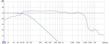
In any case it is very strange your high frequency response if compared with my wiuthout filter. Which horn are you using ?
The inital idea was to keep the crossover point the lowest possible to avoid the direction problems of this large woofer.
A 2.5KHz point is good for a max 20cm diameter woofer.
Could you make all measurement with 10dB step and at 30 grade?
In any case it is very strange your high frequency response if compared with my wiuthout filter. Which horn are you using ?
Here the compare with 341ms and 85ms.
I cannot set less than 5ms on Clio system.
My crossover point nowis about 1.5KHz.
You have crossover point in the human voice frequency range 500 to 2K which is very hard to do.
How do male and female voices sound?
Last edited:
apelizzo,
The inital idea was to keep the crossover point the lowest possible to avoid the direction problems of this large woofer.
A 2.5KHz point is good for a max 20cm diameter woofer.
Could you make all measurement with 10dB step and at 30 grade?
In any case it is very strange your high frequency response if compared with my wiuthout filter. Which horn are you using ?
I'm using the DDS spherical waveguide and I have to equalize the response. That's why three pole filter.
You have a good point regards to the direction problem of this large woofer. I will measure as you suggest with 10dB step and at 30 grade
The high frequency response is measure in the throat right to the driver metal grid. It is similar to the Beyma chart which shows a sort of slope from 2K to 20K
Last edited:
apelizzo,
The inital idea was to keep the crossover point the lowest possible to avoid the direction problems of this large woofer.
Then I would use 3 order filtering to avoid distortion of the large xmax in the HF driver and to prevent damage.
I did some work on the filter this day works fine.
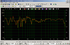
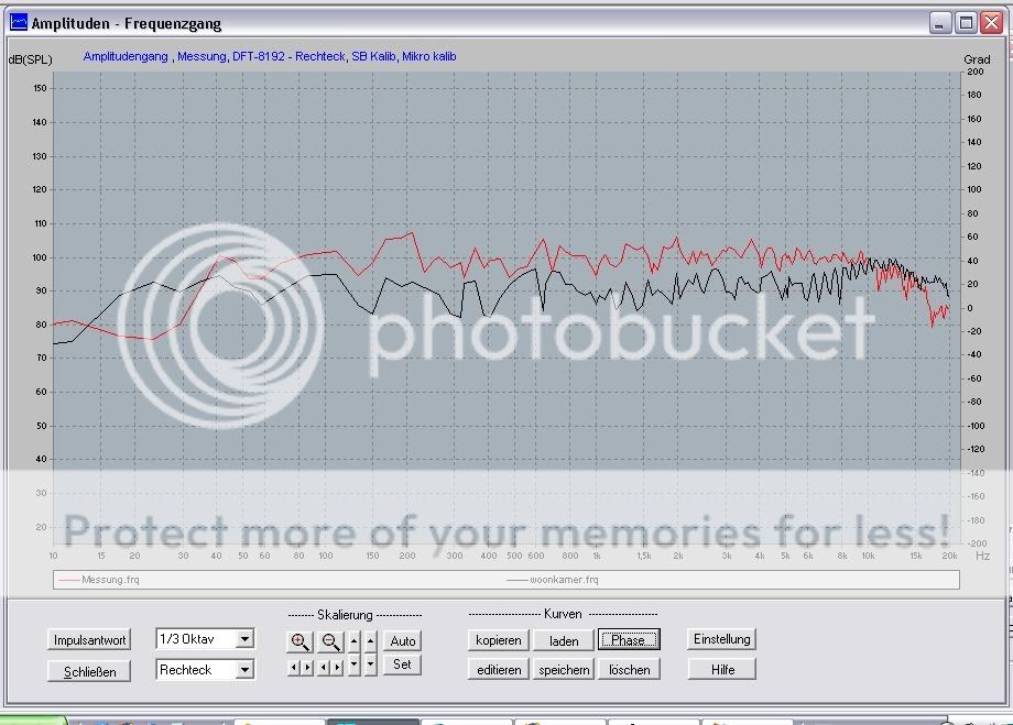
Here a stereo measurement in my living room 170msec, the loud speaker needs a super tweeter that will be added soon. The horn is simulated to have a spl 110-105dB.
I can not tell for sure but when I look at the SPL level of the HF horn it shout do 102-105dB 1wmtr and down to 35Hz!!.
Last edited:
the loud speaker needs a super tweeter that will be added soon.
You can hear past 16KHz?
apelizzo,
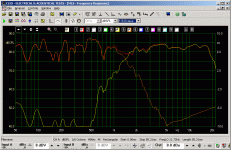
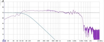
You are using DDS spherical waveguide instead of the my Stereo-Lab horn with a very flat frequency response (see plot) so we cannot use the same filter.
My idea was to use the compression band in the most wide frequency range like the hi-end japan design.
The target for these designs should be use a 2" horn to start from 500Hz but the cost are more high.
Using 1" at 1KHz there is no problem of max power because this system will be driven by single ended amplifiers with 5-20w.
We are not designing a system for PA.
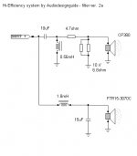
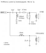
Here the new 1.2KHz filter.
You are using DDS spherical waveguide instead of the my Stereo-Lab horn with a very flat frequency response (see plot) so we cannot use the same filter.
My idea was to use the compression band in the most wide frequency range like the hi-end japan design.
The target for these designs should be use a 2" horn to start from 500Hz but the cost are more high.
Using 1" at 1KHz there is no problem of max power because this system will be driven by single ended amplifiers with 5-20w.
We are not designing a system for PA.
Here the new 1.2KHz filter.
Attachments
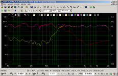
To compare the stereo mesurement, I added the stereo result of my previous set. The Bandpass project Fatboy the black line.
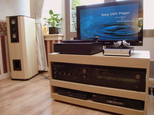
Picuture of the fatboy loudspeaker and the restored Wega Vfet amplifier and tuner .
Topic fatboyhttp://www.diyaudio.com/forums/multi-way/137036-big-bandpass-fatboy.html
Topic Vfet.http://www.diyaudio.com/forums/solid-state/149260-v-fet-repair-wega-v4810-solid-state-heaven.html
And an other speaker project of me.
http://www.diyaudio.com/forums/multi-way/130857-high-end-3-way-dappolito-aluminiumcone.html
Last edited:

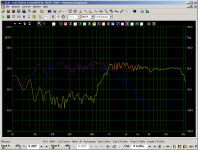
1KHz filter
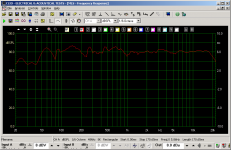
Looks nice did you reverse the polarity of the HF driver to match the phase. I do not wont to doubt your skills only to check. When I see the grafic it looks fine.
I like the looks of your Onken enclosure a massive box and multiplex looks nice to.

Last edited:
??Both drivers in these measurements are with the same phase
The low 2 order filter will shift the phase -90 to -180 degrees >1kHz.
The High 3 order filter will shift the phase 180 to 0 degrees >1kHz.
at 1 Khz they are oposite and will kill all sound in that region.
So when you reverse the polarity of one driver I would choose the HF driver then it has also -180 degrees phase above 1Khz.
Low < 1 kHz -90 to 0 degrees.
High < 1 khz -180 to -90 degrees , the phase becomes reversed 0 to 90 degrees
So when one driver has reverse polarity the drivers will have more matching phase. maximum difference 90 degrees as in your situation you have 180 degrees shift. Opposite phase

Regards Helmuth
Last edited:
- Home
- Loudspeakers
- Multi-Way
- Hi-End and Hi-Efficency loudspeakers (horn + onken)