Not always strictly true, although this is often a default method. In principle, the acoustic centre (if known) should be defined as the point of rotation. That might be in a different location for the various elements of a multi-way speaker or at the diaphragm for certain types of high-frequency horns.Needs to be rotating on the edge of the front baffle, otherwise the distance won't be constant.
As an example, the point of rotation that was used for a particular set of directivity measurements is explicitly defined on a per-speaker basis in the Meyer Sound MAPP3D coverage prediction software:
https://mapp-3d-help.meyersound.com/loudspeakers/
This ProSoundWeb article has an example of a common approach to choosing the appropriate point of rotation for a multi-way speaker:
https://www.prosoundweb.com/accurat...-measurements-for-loudspeaker-modeling-files/
Yes, it is always strictly true because of simple geometry math, distance vs SPLNot always strictly true, although this is often a default method. In principle, the acoustic centre (if known) should be defined as the point of rotation. That might be in a different location for the various elements of a multi-way speaker or at the diaphragm for certain types of high-frequency horns.
As an example, the point of rotation that was used for a particular set of directivity measurements is explicitly defined on a per-speaker basis in the Meyer Sound MAPP3D coverage prediction software:
View attachment 1044491
https://mapp-3d-help.meyersound.com/loudspeakers/
This ProSoundWeb article has an example of a common approach to choosing the appropriate point of rotation for a multi-way speaker:
View attachment 1044492
https://www.prosoundweb.com/accurat...-measurements-for-loudspeaker-modeling-files/
We are not interested in the acoustic center of a specific transducer, but of the whole system.
Two totally different things, stay on the subject please.
Moving the turning point vertically as shown in those picture, is the same thing as moving the mic up, but still let the speaker rotate around de front of the baffle. Or just tilting the speaker (vertically)
Besides that, it's cheating the off-axis response or directivity (and some companies are known for doing these kind of things and making it sound fancy in a nice marketing story)
In the case of how I do measurements, I have analyzed the situation and found that there is no difference in the predicted far field data for any rotation point that is within the sphere of the measurements. (For those interested, this is a direct result of Green's theorem.) This is because the nearfield is analyzed using polar modes and will correctly capture any source within the sphere when propagated to the far field. This is also true of Klippel's system.
I don't know for sure, but I suspect that not using modal expansion will allow for errors.
I don't know for sure, but I suspect that not using modal expansion will allow for errors.

Yes, it is always strictly true because of simple geometry math, distance vs SPL
We are not interested in the acoustic center of a specific transducer, but of the whole system.
Two totally different things, stay on the subject please.
I think kyleneuron was OT, and saying we are interested in the acoustic center of the system.
Delays can align the various individual drivers TO's to a single axis, but will misalign to some extent under any rotation, unless the physical stacking of drivers acoustic centers is in line (and need no delays).
Ime, when measuring far-field outdoors, the least variance in driver's individual TOF's comes when rotating over the system's mean acoustic center.
However, the best measured phase traces come when rotating around the CD's (the HF/VHF) sections acoustic center.
Simple reason being, as individual driver's relative distance changes under rotation if not geometrically stacked, the longer the wavelength, the less the degrees of phase impact.
I think this is a case where better phase measurements are maybe fibbing, and the mean acoustic center and measured TOFs are better truth.
I don't buy into the idea you can just chose any rotation point......unless polar optimizing software knows exactly what's going on...which i don't buy into yet LOL
I think this is what bforce is saying
When the front centre of the baffle is used as the rotation point the measurement distance is kept equal when rotated, the black line.

When an offest position is chosen as the rotation point the length of the black line to the speaker baffle/edges changes, it is the same to the point of rotation but the speaker itself gets in the way.

When the front centre of the baffle is used as the rotation point the measurement distance is kept equal when rotated, the black line.
When an offest position is chosen as the rotation point the length of the black line to the speaker baffle/edges changes, it is the same to the point of rotation but the speaker itself gets in the way.
I meant to say i think kyleneuron was OnTopic, not off. I blew the abbreviation.
I'm inclining to think the speaker does get in the way, no matter where the POR. I mean, how else could we measure rearward radiation, or a Synergy outside it's H-V pattern?
So, i stick with trying to rotate over the speaker's acoustic center, after using delays to vertically stack drivers' acoustic centers as best as possible.
Best ground plane rotation (I think) i've found, is to measure on an inclined driveway. I try to match the fall of the driveway over the measuring distance, to the height of the point on the speaker between drivers centers that i wish to be the reference for vertical rotations. Then i shim the turntable level, which is down below the mic, and hope a level line forms from the mic on the ground to speaker's vertical reference point. Seems to give ground plane measurements with an aiming tilt, and allow rotations around the speaker's acoustic center. Hope that made sense...
In the far-field, yes. The inverse distance rule doesn't apply in the near-field, so 'simple geometry maths' isn't necessarily going to be correct. Small offsets in timing may become much more noticeable in this region too.Yes, it is always strictly true because of simple geometry math, distance vs SPL
Everything I've read in this thread so far indicates that camplo will be listening exclusively in the near field - if the speakers are ever finished 😀
I agree, hence sharing the links and the image indicating where the combined acoustic centre is likely to be for a two-way cabinet with HF horn and direct-radiating LF driver.We are not interested in the acoustic center of a specific transducer, but of the whole system.
If you're only making a polar map of the magnitude response, then pick whatever rotation point you like. If you're developing crossovers or filtering, then you want complex data, and using the correct point of rotation is important.
To quote from Charlie Hughes:
If our measurements contain complex data (e.g., magnitude and phase) it’s possible to deal with the POR not being coincident with the acoustic center, up to a certain point. The measured phase data can act as an error correction mechanism for the offset distance between the POR and the acoustic center of the DUT.
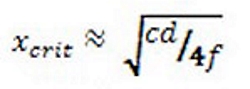
Equation 6: Critical distance based on measurement distance.
Note that this data must be the actual measured phase response of the DUT, not the phase response derived from the Hilbert transform of the magnitude-only data. There’s a limit to the offset distance that the phase data can effectively handle, which can generally be stated as a maximum of one-quarter wavelength at the highest frequency of interest.
There's some good information on the entire process including choosing an appropriate measurement distance, but skip to page 2 of the article if you want to the part about setting the point of rotation for crossover development.
For a soft dome HF mounted directly on the baffle, then the front edge is fin. You can also do more complex sources this way, but you may find errors in the data if not handled correctly.
It may matter less if you can place the receiver at a distance that ensures you're in the far-field for all sources, at all frequencies of interest. I've yet to work in an anechoic chamber that huge myself though, and I'm not sure one exists.
The point of rotation is shifted both on the Y-axis and the Z-axis on the diagram.Moving the turning point vertically as shown in those picture, is the same thing as moving the mic up, but still let the speaker rotate around de front of the baffle. Or just tilting the speaker (vertically)
When actively-processed loudspeakers are measured to acquire their 3D balloon data, the process is repeated for each source solo, without any filtering applied. The filtering is then modelled and optimized in software, while viewing the impact on polar response.
This is one of the major features of VituixCAD, and you don't have to spend AFMG SpeakerLab money to get it - although you do only get access to horizontal and vertical behaviour, not the full balloon.
I do completely understand the concerns about the cabinet 'blocking' the output, but it can be argued that this is a fundamental part of using a physical device such as a horn or waveguide to define directivity.
If you have Glen Ballou's Handbook for Sound Engineers, read Chapter 35 Computer Aided Sound System Design by Dr. Wolfgang Ahnert, Stefan Feistel and Hans-Peter Tennhardt, where the two quotes below come from.I don't buy into the idea you can just chose any rotation point......unless polar optimizing software knows exactly what's going on...which i don't buy into yet LOL
For single drivers or horns rotating about the acoustic centre makes total sense, and in a speaker that you like, active with delay and FIR crossovers, there isn't any real group delay to mess that up. If you use a program to predict and model the crossover then following the advice of the developer will cause less headaches. For Vituix that is baffle front unless a stepped baffle is used then it changes.
"The error is maximal for measurements where the connecting line between microphone and POR passes through both POR and acoustic source, in this case, at an angle of 90 degrees. Nevertheless, for all practical cases the error is largely negligible. For example, typical values of x = 0.1 m and d = 4 m yield an error of only 0.2 dB".I don't know for sure, but I suspect that not using modal expansion will allow for errors.
"Assuming that the phase response will be usually dominated by a run-time phase component due to one or several acoustic sources being located away from the POR, conditions for the spatial and spectral density of data points can be computed....
As an example, these limits correspond roughly to a measurement setup where the acoustic source is not farther away than ca. 0.15 m from the POR. Phase data points will be close enough up to a frequency of 8 kHz, if the frequency resolution is at least octave (or 475 Hz) and the angular resolution is at least 5 degrees."
The full paper by those fellas gives a more in-depth explanation of modelling filters on complex balloon data, and most importantly advice on the method:
https://www.aes.org/e-lib/browse.cfm?elib=14312
This might also be useful; how to determine physical location from complex phase data:
https://www.prosoundweb.com/phase-response-receive-delay/
I strongly advise reading all of his PSW articles. You can find them using a link next to his profile at the bottom of the page.
Charlie's write-up is based on the AES paper, since he previously worked closely with AFMG and has created quite a lot of crossovers and GLL files in his time. I'm not sure if that's still the case, since he joined a company full-time a few months ago.
I was responding from a general point of view.In the far-field, yes. The inverse distance rule doesn't apply in the near-field, so 'simple geometry maths' isn't necessarily going to be correct. Small offsets in timing may become much more noticeable in this region too.
Everything I've read in this thread so far indicates that camplo will be listening exclusively in the near field - if the speakers are ever finished 😀
I agree, hence sharing the links and the image indicating where the combined acoustic centre is likely to be for a two-way cabinet with HF horn and direct-radiating LF driver.
If you're only making a polar map of the magnitude response, then pick whatever rotation point you like. If you're developing crossovers or filtering, then you want complex data, and using the correct point of rotation is important.
To quote from Charlie Hughes:
There's some good information on the entire process including choosing an appropriate measurement distance, but skip to page 2 of the article if you want to the part about setting the point of rotation for crossover development.
For a soft dome HF mounted directly on the baffle, then the front edge is fin. You can also do more complex sources this way, but you may find errors in the data if not handled correctly.
It may matter less if you can place the receiver at a distance that ensures you're in the far-field for all sources, at all frequencies of interest. I've yet to work in an anechoic chamber that huge myself though, and I'm not sure one exists.
The point of rotation is shifted both on the Y-axis and the Z-axis on the diagram.
When actively-processed loudspeakers are measured to acquire their 3D balloon data, the process is repeated for each source solo, without any filtering applied. The filtering is then modelled and optimized in software, while viewing the impact on polar response.
This is one of the major features of VituixCAD, and you don't have to spend AFMG SpeakerLab money to get it - although you do only get access to horizontal and vertical behaviour, not the full balloon.
I do completely understand the concerns about the cabinet 'blocking' the output, but it can be argued that this is a fundamental part of using a physical device such as a horn or waveguide to define directivity.
People read along and don't understand the nuances with nearfield or farfield listening. There is already to much misinformation in this world, so it's very important to get those nuances right.
What's even more important is that people actually doing these measurements and experience the practical part of it.
If you have Glen Ballou's Handbook for Sound Engineers, read Chapter 35 Computer Aided Sound System Design by Dr. Wolfgang Ahnert, Stefan Feistel and Hans-Peter Tennhardt, where the two quotes below come from.
Yep, thx for pointing me to it. Ch 39 in 5th edition.
"The error is maximal for measurements where the connecting line between microphone and POR passes through both POR and acoustic source, in this case, at an angle of 90 degrees. Nevertheless, for all practical cases the error is largely negligible. For example, typical values of x = 0.1 m and d = 4 m yield an error of only 0.2 dB".
Looking at the article's diagram that goes with that quote, it appears the x values is the distance between acoustic centers.
If that's correct, the quote doesn't make sense to me. Getting acoustic centers within 0.1m seems about impossible with any standard baffle design.
"Assuming that the phase response will be usually dominated by a run-time phase component due to one or several acoustic sources being located away from the POR, conditions for the spatial and spectral density of data points can be computed....
As an example, these limits correspond roughly to a measurement setup where the acoustic source is not farther away than ca. 0.15 m from the POR. Phase data points will be close enough up to a frequency of 8 kHz, if the frequency resolution is at least octave (or 475 Hz) and the angular resolution is at least 5 degrees."
I don't understand what he means by frequency resolution at least one octave (or 475 Hz).
And have to continue to question the distance from POR..????
My main take away from the article re simulations, is that complex far-field data is needed for each driver, and the simulation software has to talk the same language as the measurements.....(like you mentioned keeping it all within VituixCad.)
Second take away, is all the simplifying assumptions that are still in play even after that....ie point source, spherical wave, etc etc,
I do love measurement based tuning....but remain a bit skeptical there too.
My favorite quote in Erin's interview with C. Bellmann of Klippel, is shortly after the 16:30 mark,..."i actually believe no measurement !"
I think that is the version that has a chapter from Tom Danley?Yep, thx for pointing me to it. Ch 39 in 5th edition.
I can see why that diagram might be confusing I think it is referring to the distance between the point of rotation and acoustic centre.Looking at the article's diagram that goes with that quote, it appears the x values is the distance between acoustic centers.
If that's correct, the quote doesn't make sense to me. Getting acoustic centers within 0.1m seems about impossible with any standard baffle design.
"Given these parameters, X-crit is the maximal distance allowed between the POR and the acoustic source at the given frequency resolution".
This corresponds with the image from Charlie Hughes posted above where two circles intersect giving a range where the measurement will have the least error.
Sorry that was a bad copy on my part the frequency resolution is 1/12 octave, it was written as a symbol in the book which didn't copy over.I don't understand what he means by frequency resolution at least one octave (or 475 Hz).
And have to continue to question the distance from POR..????
So the quote should have read "at least 1/12 octave (or 475Hz)".
They also say thisMy main take away from the article re simulations, is that complex far-field data is needed for each driver, and the simulation software has to talk the same language as the measurements.....(like you mentioned keeping it all within VituixCad.)
"We emphasize that the use of phase data does not only reduce the error in the directivity data but it also largely eliminates the need to define, find, and use the so-called acoustic center, the imaginary origin of the far-field spherical wave front".
I think that is the version that has a chapter from Tom Danley?
I can see why that diagram might be confusing I think it is referring to the distance between the point of rotation and acoustic centre.
"Given these parameters, X-crit is the maximal distance allowed between the POR and the acoustic source at the given frequency resolution".
This corresponds with the image from Charlie Hughes posted above where two circles intersect giving a range where the measurement will have the least error.
Sorry that was a bad copy on my part the frequency resolution is 1/12 octave, it was written as a symbol in the book which didn't copy over.
So the quote should have read "at least 1/12 octave (or 475Hz)".
They also say this
"We emphasize that the use of phase data does not only reduce the error in the directivity data but it also largely eliminates the need to define, find, and use the so-called acoustic center, the imaginary origin of the far-field spherical wave front".
Thanks for the follow ups....
Yes, Tom wrote about 32 pages that span a ton of subjects, and various types of speakers.
Some things I've been wondering about...
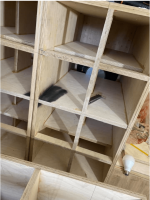
In the face of bracing and the ability to create virtually sonic inert enclosures with the approach cross bracing matrix like so;

Doesn't this open the door to use almost any plywood or particle board within reason?
1" braces every 6inches in a cross matrix is the standard per Bill Fitzmaurice allowing one to use 0.5" inch BB ply
Another similar approach using whole panels, similar to the folds of a folded horn

I combined the theories of both of these approaches, specifically using the solid panels like above combined with ideas of spacing of the matrix approach.....
I think some said "overkill"....which to me is the goal until I know the lower limit BUT again, it would seem that the material used because much less important "sonically" in this realm of "overkill" bracing.
Maybe not?
In the face of bracing and the ability to create virtually sonic inert enclosures with the approach cross bracing matrix like so;
Doesn't this open the door to use almost any plywood or particle board within reason?
1" braces every 6inches in a cross matrix is the standard per Bill Fitzmaurice allowing one to use 0.5" inch BB ply
Another similar approach using whole panels, similar to the folds of a folded horn
I combined the theories of both of these approaches, specifically using the solid panels like above combined with ideas of spacing of the matrix approach.....
I think some said "overkill"....which to me is the goal until I know the lower limit BUT again, it would seem that the material used because much less important "sonically" in this realm of "overkill" bracing.
Maybe not?
Last edited:
If you label it as perfect then maybe it sounds as though you can use paper for your walls. The answer lies in working out the limitations of the matrix.virtually sonic inert
I changed the spacing suggested by Bill F. for what was meant for 0.5", to 0.75", to scale exponentially. So 6" spacing became 9" spacing. Using full planks instead of singular crossbeams, supplies increased bracing, as well, should serve to Raise the modes of the internal dimensional based resonant notes, also theoretically beneficial to the cause.
Its hard to imagine that the outcome would be gravely different between any other plywood within 0.5 - 0.75 thickness.
maybe another way to look at it would be to say that, It Seems, no matter which reasonable Wood and thickness one used....there is likely a bracing scheme that will allow for optimal results, no less than what I have achieved with the choice wood of Baltic birch
Or maybe I don't know how bad, bad can be, what ever the "bad" choice is? Maybe solid wood?
Attachments
In the face of bracing and the ability to create virtually sonic inert enclosures with the approach cross bracing matrix like so;
Doesn't this open the door to use almost any plywood or particle board within reason?
1" braces every 6inches in a cross matrix is the standard per Bill Fitzmaurice allowing one to use 0.5" inch BB ply
Yes, if using the correct interlock and aspect ratio to meet the needs of the app, which many times in my smaller speaker builds was scrap corrugated cardboard and/or Styrofoam.
While I do believe strongly in internal bracing, I would estimate that 80% of the improvement comes with a single brace (in each of the three orthogonal directions, tied together at the center.) Adding more and more becomes superfluous at some point (probably very quickly.) I used 1" oak, but then changed to 1" poly.
Add damping to the braces and this increases it's effectiveness.
Add damping to the braces and this increases it's effectiveness.
Hi Earl,
What do you call poly? Polypropylen? Apologize but translation is sometimes confusing.
And from where comes the last 20%? Something like CLD damping of braces?
I think i remember you once talked about it in a previous thread about CLD effectiveness and if i'm right, you said you used this techniques on Summa rather than CLD on walls?
GM,
Thank you for the link! Some of them i knew, some not.
This rise a question: which one to use in which case ( i expect there is multiple possible answers, case specific)?
- Home
- Loudspeakers
- Multi-Way
- Is it possible to cover the whole spectrum, high SPL, low distortion with a 2-way?