I used polyurethane boards in all my designs. The 20% is what you get from using more than one cross brace, ie. a "matrix". Not worth the trouble IMO.
I used CLD only on the baffle board and CLD-like braces. Each brace is two pieces held together with a soft damped polyurethane. So that the damping is in shear when the walls bend. Kind of like CTD, but not exactly the same since it's not a panel.
I used CLD only on the baffle board and CLD-like braces. Each brace is two pieces held together with a soft damped polyurethane. So that the damping is in shear when the walls bend. Kind of like CTD, but not exactly the same since it's not a panel.
Ok polyurethane boards, thank you.
Which shores A have you used for it ( the boards)? On the 'hard' side ( 90)?
Braces CLD you describe is what i remembered from the thread, and i think you said this was commonly used within the industry.
Been looking at Kef and Tannoy (DMT range) and both used or use same kind of approach ( matrix and 'CLD' damping).
+1 except prefer one pre/mass loads the woofer.While I do believe strongly in internal bracing, I would estimate that 80% of the improvement comes with a single brace (in each of the three orthogonal directions, tied together at the center.) Adding more and more becomes superfluous at some point (probably very quickly.) I used 1" oak, but then changed to 1" poly.
Add damping to the braces and this increases it's effectiveness.
That is actually the way to do it. Bias will be dominate in the beginning, but as time goes on it diminishes. But then there is also "acclimation" - where we get used to and come to like whatever we have - sometimes no matter how bad it is.
I really liked this comment, though not from this thread, I think it applies to the different options that We call, The best...or the way.
I am really familiar with this concept dealing with music that I may not like at first but fall in love with later....Mouse sensitivity changes for first person shooters...different sounding stereos, etc etc
Compare and contrast seem to the best friend of enlightenment on these types of things but the process has to also include a stage that leaves behind the immediate impressions of compare and contrast of all said contenders and one must begin the process of living with, for some time each contender in order to let acclimation set in for each contender.....Hopefully taking good notes along that way.
When one is allowed to acclimate with contender B, a revisit to contender A will be very eye opening, potentially.
I argue and debate with a very bi-polar style as well...seeming to have chosen another path when really I just want to see what happens during the process of acclimation of mentally entertaining an idea for a period of time.... Almost always many truths are revealed... which is what we are all after... as well I haven't changed the design for a very long time though, have, at length, talked about transmission line....many variations of TL....dual horizontal mid 15"s... multi configurations of the 18's.... and more...
It is a good idea to find very methodical and experienced people to pull wisdom from. We are very fortunate to have access, in this forum, some very Bright minds that fit that category. Thank you! To those people, they have hung around for a long while, and I appreciate how you all seek to pick apart the details and stay constructive. It really means a lot to me.
....that is all Lol! I was going to say something about bracing but I think thats been covered pretty well...finally.
Horns are still not shipped, but I think maybe Monday or Tuesday will be the special day, and from there it should be to my Door step within a week?
|
Tomorrow is the first day back to work and I think I should be able to find time to move forward with the other goals of this project.
*Purchasing a CNC or 3d resin printer - Seems 3d printer is more programmer friendly?/
*Constructing examples of Docalis Horns.
*Constructing an OSWG
I wish I had of checked my notes before completely putting together the subwoofer, I fancy an interlocking mid section held together with many screws (Think lego's -> ] ] ) this will allow the bracing on the backside of the woofer to be permanent. Bracing in between the woofers was said to be pointless.
I also have to put vinyl on this damn thing.... think Horizontal brushed black aluminum mid and sub box with lacquer, should look decent
Actually, most people make an "open" bracing structure.While I do believe strongly in internal bracing, I would estimate that 80% of the improvement comes with a single brace (in each of the three orthogonal directions, tied together at the center.) Adding more and more becomes superfluous at some point (probably very quickly.) I used 1" oak, but then changed to 1" poly.
Add damping to the braces and this increases it's effectiveness.
But especially in a closed box, one can divide the volume in 4 exact smaller volumes with no openings between the four compartments. The compliance on the woofer should still be the same (minus the thickness of the wood obviously).
This has a huge benefit in sense of internal reflections and standing waves.
Which means that (sometimes) no damping material is needed, or the efficiency of the damping material will be a lot higher.
Technically this could also work for a BR or horn idea I think.
I would never advice real hard woods (like oak) for building any kinds of structure.
Especially oak can suffer from severe cracking when the grain structure is off (not ideal quarter sawn) plus it's very expensive.
Plywoods are a lot more resistant against temperature and humidity changes.
Ideal and superior for rigid structures.
Even better is some kind of hybrid laminated structure when looks are important.
Veneering is also an option.
^Are you assuming the driver is centered on baffle? Driver at center would already minimize the lowest modes of the two dimensions and perhaps accent the second mode where pressure node is in the middle, at the driver. At least in simulator. This situation would not be affected with the said 4 compartment scheme if I understood it correctly. Second mode(s) would now exist like before as lowest modes in the compartments and excited just like before. Lowest mode wouldn't be more problematic as it was before as the driver is still at the center of the path. Third mode would be affected most I think, but these are usually out of band already, or at least easily killed with damping. Reasoning it like so I'm afraid though that there is now only longer (folded) path length modes to form as the compartments need to be open on the corner to accommodate the driver and practically nothing changed regarding (problematic) standing waves, except perhaps it is that much more stiffer enclosure.
Last edited:
The baffle isn't relevant, we are talking about the back enclosure?^Are you assuming the driver is centered on baffle? Driver at center would already minimize the lowest modes of the two dimensions and perhaps accent the second mode where pressure node is in the middle, at the driver. At least in simulator. This situation would not be affected with the said 4 compartment scheme if I understood it correctly. Second mode(s) would now exist like before as lowest modes in the compartments and excited just like before. Lowest mode wouldn't be more problematic as it was before as the driver is still at the center of the path. Third mode would be affected most I think, but these are usually out of band already, or at least easily killed with damping. Reasoning it like so I'm afraid though that there is now only longer (folded) path length modes to form as the compartments need to be open on the corner to accommodate the driver and practically nothing changed regarding (problematic) standing waves, except perhaps it is that much more stiffer enclosure.
The first mode correlates extremely well with one can be expected from the theoretical literature and is often with bigger enclosures the hardest to get rid of when <300-500Hz, since damping materials don't do a lot anymore below those frequencies. This will be different in a case when the surface area of the speaker is small compared to the size of the box/volume. (aka the length in something like a 1 meter tall box with a woofer on just one end)
I have done dozens of measurements over decades, and this always correlates extremely well with the frequencies that one can expect. Especially in smaller sub-woofer like enclosures (were the surface area of the woofer is practically as big as the whole inner height/width of the box)
Otherwise this can be modeled quite easily to get the estimated numbers.
When halving the distance the first mode goes up double the frequency.
Shifting this first mode frequency either out of range or in an area were the damping material is more effective.
Very effective technique in subwoofers, FAST systems, 2-way midwoofer systems etc.
Also keep in mind that damping material does react on a less linear way (non-linear).
Anyway, this was just some free advice and tips, based on things I measured and knowledge I gained over many years.
Cross correlated with one can expect from theory.
I am not going into theoretical debates about it, especially not about very specific cases.
Than you're missing the bigger picture of it all and I would highly recommend first doing some measurements to begin with.
For sure, standing waves, the modes, depend on the box dimensions. It is the solid divider panels you mentioned that got my interest and was wondering how it works out in real world, how a box with such panels would measure. If you have time please checkout clarification below what I ment with the previous post. I'd be delighted if you have time to check it and post comments on it, with connection to reality. These thoughts are based on sims and reasoning, I haven't done prototyping / listening specifically for this issue.
Alright, first assume the lowest mode wavelength is so long that anything that fits into the enclosure does not affect it much, perhaps a little but can't stop it. Hence reasoning divider panels just make even longer path lengths inside the box making the problem even worse, more into pass band and damping is less effective. A solid divider changes the dimensions, as if the box was now folded. See images here as illustration for folded horns http://www.diysubwoofers.org/sheets/
Here is simulation that demonstrates the lowest mode/first harmonic can be killed just by putting the driver to the center of the dimension, at velocity node of a standing wave. Sorry about confusion with previous post where I wrote center of the baffle, it was due to thinking the simulation visualization.

I imagined your example solid divider panels like so: driver in the middle of two dimensions (baffle), then one solid vertical and one solid horizontal divider panel inside the box. To make room for the driver the panels must have cutout for the driver frame. Now if the baffle was removed the innards would look like four equal sized smaller "boxes", is this what you ment? Thinking the modes inside of such enclosure they would be about the same as without the divider panels because the horizontal panel doesn't do much to the lowest mode because it is acoustically small, less than half wavelength at best. If it does affect, like with folded horns, there is now perhaps even a little bit longer path length in addition, like so:

Dividers at middle dimension would make lowest mode which is equal to second lowest mode without the divider.
Either way reasoning based on the sims and assumption that folded horns work the conclusion is panels like these don't do practically anything to the harmonics inside a box other than possibly making more of them, and perhaps making the longest dimension even longer. In this example all of this doesn't really matter because the driver is middle of the long path length and horizontal panel is middle of the box so all the excited modes list about the same with or without the divider panels.
If the reasoning is valid then here is some things one can actually do to take care of the internal standing waves:
Make a cube to maximize internal volume for the use case while pushing all the modes up in frequency and perhaps above pass band, works nice for subwoofers. Tower would be worst, modes get low in frequency due to long dimension and harder to deal with than with a cube with same volume. Lowest mode can be prevented by placing the driver middle of the dimension while damping material is effective on the higher modes. Woofer at the end of a dimension will maximally excite all modes so it is worst possible position for a woofer. Depth of the box should be minimal as here the woofer is at the end of that dimension, minimal depth might push even the lowest mode between baffle and back panel above pass band, even with mid woofers crossing to a tweeter. Alternatively depth could be very long to fit enough damping between to kill even the lowest mode. Or perhaps more elegantly one could put another driver on the back panel so that acoustic center becomes center of the volume dealing with all lowest modes within the box while enjoying some push-push configuration force cancellation as bonus. Or some resonators, what have we.
In reality, I don't know what is good enough, maybe any of this doesn't matter much. I would guess that if there is audible problems with internal standing waves it is the lowest mode (of any dimension) because it is most likely on the pass band and least affected by any damping. Position the driver seems to be most effective way to deal with it. Or is the problem when the pressure node happens at the driver? In this case middle wouldn't be the best place for driver as second lowest mode would have strong excitation and pressure node there. Either case shallow depth would benefit.
Alright, first assume the lowest mode wavelength is so long that anything that fits into the enclosure does not affect it much, perhaps a little but can't stop it. Hence reasoning divider panels just make even longer path lengths inside the box making the problem even worse, more into pass band and damping is less effective. A solid divider changes the dimensions, as if the box was now folded. See images here as illustration for folded horns http://www.diysubwoofers.org/sheets/
Here is simulation that demonstrates the lowest mode/first harmonic can be killed just by putting the driver to the center of the dimension, at velocity node of a standing wave. Sorry about confusion with previous post where I wrote center of the baffle, it was due to thinking the simulation visualization.
I imagined your example solid divider panels like so: driver in the middle of two dimensions (baffle), then one solid vertical and one solid horizontal divider panel inside the box. To make room for the driver the panels must have cutout for the driver frame. Now if the baffle was removed the innards would look like four equal sized smaller "boxes", is this what you ment? Thinking the modes inside of such enclosure they would be about the same as without the divider panels because the horizontal panel doesn't do much to the lowest mode because it is acoustically small, less than half wavelength at best. If it does affect, like with folded horns, there is now perhaps even a little bit longer path length in addition, like so:
Dividers at middle dimension would make lowest mode which is equal to second lowest mode without the divider.
Either way reasoning based on the sims and assumption that folded horns work the conclusion is panels like these don't do practically anything to the harmonics inside a box other than possibly making more of them, and perhaps making the longest dimension even longer. In this example all of this doesn't really matter because the driver is middle of the long path length and horizontal panel is middle of the box so all the excited modes list about the same with or without the divider panels.
If the reasoning is valid then here is some things one can actually do to take care of the internal standing waves:
Make a cube to maximize internal volume for the use case while pushing all the modes up in frequency and perhaps above pass band, works nice for subwoofers. Tower would be worst, modes get low in frequency due to long dimension and harder to deal with than with a cube with same volume. Lowest mode can be prevented by placing the driver middle of the dimension while damping material is effective on the higher modes. Woofer at the end of a dimension will maximally excite all modes so it is worst possible position for a woofer. Depth of the box should be minimal as here the woofer is at the end of that dimension, minimal depth might push even the lowest mode between baffle and back panel above pass band, even with mid woofers crossing to a tweeter. Alternatively depth could be very long to fit enough damping between to kill even the lowest mode. Or perhaps more elegantly one could put another driver on the back panel so that acoustic center becomes center of the volume dealing with all lowest modes within the box while enjoying some push-push configuration force cancellation as bonus. Or some resonators, what have we.
In reality, I don't know what is good enough, maybe any of this doesn't matter much. I would guess that if there is audible problems with internal standing waves it is the lowest mode (of any dimension) because it is most likely on the pass band and least affected by any damping. Position the driver seems to be most effective way to deal with it. Or is the problem when the pressure node happens at the driver? In this case middle wouldn't be the best place for driver as second lowest mode would have strong excitation and pressure node there. Either case shallow depth would benefit.
Last edited:
What happens with those results when you lower csa and increase length to keep volume static? From my recollection... there is a change, one of them being, the increase of efficacy in damping material... That sim would closer represent what happens when dividing up the box as you guys are discussing, I would think
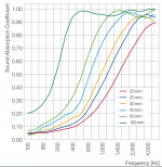
Yes with longer dimension more damping material fits in, making it more effective at lower frequency. b_force already mentioned ramping material linearity of absorption, which I think he means that lows are absorbed less than highs. This is true, some materials are more effective for lows than others. But, there are many things that affect effectiveness like incident angle, thickness of the material and airspace behind. Anyway, by increasing thickness the absorption affects lower in frequency and effectiveness of damping (thickness) seems to be roughly relate to wavelength. If small box requires quarter fill of material x to kill lowest mode then about quarter is enough if the system was scaled up ten fold, even though the mode is now lower in frequency the material is more effective having more thickness to it. What ever the case the lowest mode requires most fill and the lower it is the more is required.
Attached is BASF Basotect absorption coefficients for various thicknesses measured in impedance tube. Got if from here https://plastics-rubber.basf.com/global/en/performance_polymers/products/basotect.html
Attached is BASF Basotect absorption coefficients for various thicknesses measured in impedance tube. Got if from here https://plastics-rubber.basf.com/global/en/performance_polymers/products/basotect.html
Attachments
Last edited:
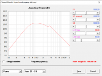
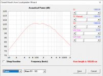
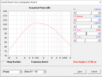
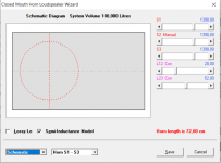
It takes long time to compile the screenshotsWhat happens with those results when you lower csa and increase length to keep volume static?
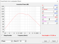
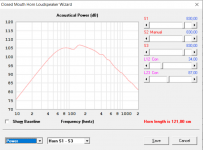
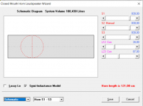
 so here is random bunch attached. All are ~100l internal volume, csa is reduced and length increased. Basically, as the enclosure is elongated keeping the fill the same (roughly ~450g of polyfill in the simulator distributed 100% of the volume in the example) the lowest modes seem visually little bit worse with elongated box, perhaps they are roughly the same here in the sims as I wasn't accurate with the driver position. Lowest mode, or any mode, can be prevented by moving the driver position. Again, the take away is that killing the lowest mode requires most fill, or at least positioning of the fill, all the higher modes are damped long before. Position driver close to center to kill the lowest mode, for least amount of damping material required to smoothen all the modes. Don't elongate the box to get remaining modes out of pass band to get away with even less damping material.
 Not sure if any of these are audible, or which ones are more audible than others, is it that any mode is audible or is it the modes that have pressure node at driver position that are audible. I would guess that on a reflex system any of the modes could leak from the port and be audible, but on a closed box like the examples perhaps some modes are more audible than others, if no damping is used.
Attachments
-
 fill.png12.8 KB · Views: 50
 -
 longest-power-with-centered-driver.png19.8 KB · Views: 48
 -
 longest-power-with-offset-driver.png20.3 KB · Views: 45
 -
 longest-same-fill-offset-driver.png14.2 KB · Views: 46
 -
 elongated-driver-about-middle-same-fill.png19.9 KB · Views: 56
 -
 elongated-offset-driver-same-fill.png20.3 KB · Views: 50
 -
 close-enough-middle-first-mode-gone-with-the-fill.png20.4 KB · Views: 45
 -
 two-way-box-with-some-fill.png15.4 KB · Views: 53
When you double the wall thickness of the cabinet you increase the area moment of inertia of your panel by a factor of 8 as I=w*t³/12 with t as thickness and w as your width.
If you brace the cabinet, your panel length halves in the calculation and you'll effectively have a two span beam with better stiffness than single span beam. If you run the numbers you'll get a deflection which is 40 times lower than in the non braced case.
Conclusion: bracing is about five times stiffer than doubling the wall thickness.
(I'm a german structural engineer, so excuse me if the wording is wrong, i used google translator for the technical terms)
Couldn't @Hornstudio help you out? It seemed like he had the experience to get things done right...
I passed his information on to LMH but I don't know if they took advantage
we almost had shipping through UPS to my door but they only ship to businesses
so this other company will ship to Detroit without the limitation...LMH says I need to find and pay for a broker to move forward.
we almost had shipping through UPS to my door but they only ship to businesses
so this other company will ship to Detroit without the limitation...LMH says I need to find and pay for a broker to move forward.
I mean I can drive to Detroit... as inconvenient as it may be... its just this broker stuff I am new tooAnyone on here from Detroit that we know?
When you say "ask for an offer" what is this?
door to door is that UPS? Ok you answered that lol
did LMH ever reach out to you?
Maybe this is something I can set up from UPS SCS here in michigan?
Probably the best question is where is this door to door link located?🤣
door to door is that UPS? Ok you answered that lol
did LMH ever reach out to you?
Maybe this is something I can set up from UPS SCS here in michigan?
Probably the best question is where is this door to door link located?🤣
Last edited:
- Home
- Loudspeakers
- Multi-Way
- Is it possible to cover the whole spectrum, high SPL, low distortion with a 2-way?