Just keep in mind that linkwitz transform was specifically designed for closed boxes (with 12 dB/oct roll off) and may not be exactly suitable for open baffle (6 dB/oct roll off).
Yes. I worked out a page on gradient woofer active EQ (OB) years ago.
http://musicanddesign.speakerdesign.net/Gradient_woofer_eq.html
I've been enjoying my open baffle stand mounts for awhile now. I live in an apartment, so my neighbours appreciate the dipole cancelation laterally and vertically.I’ve always wondered if you use subs with these OB designs, especially Bitches Brew. I think you may be right about wasted energy, especially after the 12db/oct loss and increased excursion. But for film or dance music, it can be quite noticeable, having deep subsonic tones.
I highpass my power amp with a single cap per channel, and use an H frame sub for bass with great pitch but without the ground penetrating sonics when I used the same drivers in a ported enclosure.
That's an incredibly compelling reason to go OB, @MITsound. I know the rule changes for rear wall distance depending on the person you're asking, their experience, the weather, magnetism, what their turbo encabulator says, but what do you do? My boxes live 2ft from the rear and that's only if I measure directly from the port angle directly to the backsplash. There's not a ton of wiggle room besides the 18" of box length to remove.
Very, very exciting thread!
Nowadays achieved a listenable OB, actually a SLOB, with a "full range" and a complementer woofer. The woofer has got a 3rd order lowpass filter somewhere around 200Hz.
My question is whether changing the filter to a 2nd order lowpass, a similar "boost" effect could be achieveable? Lowering the x point could also be an option to taylor the graph. (the woofer is a field coil one, with adjustable parameters)
Can you draw a graph of what you have in mind? You can design a peak into the second order low pass, but the peak would be at 200 Hz and I’m not sure that would be useful.
Very, very exciting thread!
Nowadays achieved a listenable OB, actually a SLOB, with a "full range" and a complementer woofer. The woofer has got a 3rd order lowpass filter somewhere around 200Hz.
My question is whether changing the filter to a 2nd order lowpass, a similar "boost" effect could be achieveable? Lowering the x point could also be an option to taylor the graph. (the woofer is a field coil one, with adjustable parameters)
One can achieve a boost at the crossover point using a third order lowpass filter as well. Do you know the component values of the current low pass filter?
Perrymarshall,
Boost at around 200Hz would not be beneficial indeed, but I wrote I can decrease the X-over point to 80-100Hz and adjust the fullrange accordingly.
But this X-over point is not a real X-over point, since the fullrange doesn't have an electronic highpass filter.
Mboxler,
L1: 10mH, C:220uF, L2:3,3mH, well, its rather a 150Hz LP, not 200Hz. (Re: 6,3Ohm) And yes, there is a hump at around 150Hz in the frequency response, but not that high.
I simulated a third order low pass that ultimately ends up with an equal slope. It consists of 5mh, 300uf, 5mh (BLUE).
The price you pay is that you end up with an impedance dip below 2 ohms ((RED).

The price you pay is that you end up with an impedance dip below 2 ohms ((RED).
All, I just posted a tech note here regarding the Bitches Brew Live Edge Dipole series crossover network. It presents some new angles about bass boost from passive crossover networks. Which can be either good or bad depending on what you are trying to achieve.
Mboxler,
Thanks for the simulation! Could you please simulate an X-over where the hump is at about 100Hz? Fortunately I use diy inductors with airgaped cores so the inductance can be changed easily or I can produce others ...
Thanks for the simulation! Could you please simulate an X-over where the hump is at about 100Hz? Fortunately I use diy inductors with airgaped cores so the inductance can be changed easily or I can produce others ...
These are simulations across an 8 ohm resistor, just to be clear.
Here's one using 7.5mh 400uf 7.5mh

Here's one using 7.5mh 400uf 7.5mh
Very interesting thread. Even if some of it is a bit beyond me. !
Would a woofer of Fs 26Hz but Qts 0.36 be worth adding the circuit to. ? When does the Qts become too low to make it viable?
Thanks
Would a woofer of Fs 26Hz but Qts 0.36 be worth adding the circuit to. ? When does the Qts become too low to make it viable?
Thanks
@jimk04 below 0.5 is problematic. 0.5 means driver in an infinite baffle is down -6dB at resonance. Lower than that means it's down even more. 0.36 = -8.9dB and the LC circuit boost can't overcome that. The LC circuit can add about 4-7dB boost, sometimes a bit more.
Low Q drivers are just fine if you have active / DSP and in fact I prefer them. (You also need to add subsonic protection.)
But for passive you need higher Q drivers, and the passive bass boost circuit helps a great deal.
Low Q drivers are just fine if you have active / DSP and in fact I prefer them. (You also need to add subsonic protection.)
But for passive you need higher Q drivers, and the passive bass boost circuit helps a great deal.
Last edited:
Dang it! Not to worry. Thanks for your help and advice. I do get a lot of inspiration from your projects.
Hi,
the bass peak, or boost, happens when impedance in series with the driver at driver main resonance frequency is increased so that electrical damping is reduced. Now the driver does not EQ itself anymore (through backEMF) and system Q goes up. It works for any Qts driver, but perhaps this particular application on this thread requires some particular Q. Still, the "boost" is there available for any Qts and exploitable in any system if necessary, although perhaps not very practical if Qts is already past 1.
One can test this directly in VituixCAD enclosure tool for closed boxes, select a driver and toggle the series cap on the filter tab. It should work similarly with OB as it is function of the electrical damping and adjusted/exploited per project, if it's something useful.
On these images the overlay trace in SPL window is "auto aligned" closed box response for each driver, and the black line shows response with 470uf series cap added. One can tailor the Q with box size and cap size. These are some random drivers with few different Qts to demonstrate, nothing special.
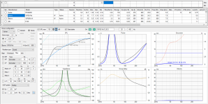
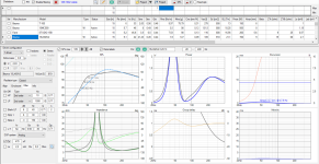
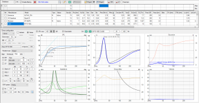
The trick increases excursion which increases distortion for the whole bandwidth so it's not free lunch. Excursion and thus distortion would rise with DSP as well so in that sense it's nice, bass boost without DSP.
the bass peak, or boost, happens when impedance in series with the driver at driver main resonance frequency is increased so that electrical damping is reduced. Now the driver does not EQ itself anymore (through backEMF) and system Q goes up. It works for any Qts driver, but perhaps this particular application on this thread requires some particular Q. Still, the "boost" is there available for any Qts and exploitable in any system if necessary, although perhaps not very practical if Qts is already past 1.
One can test this directly in VituixCAD enclosure tool for closed boxes, select a driver and toggle the series cap on the filter tab. It should work similarly with OB as it is function of the electrical damping and adjusted/exploited per project, if it's something useful.
On these images the overlay trace in SPL window is "auto aligned" closed box response for each driver, and the black line shows response with 470uf series cap added. One can tailor the Q with box size and cap size. These are some random drivers with few different Qts to demonstrate, nothing special.


The trick increases excursion which increases distortion for the whole bandwidth so it's not free lunch. Excursion and thus distortion would rise with DSP as well so in that sense it's nice, bass boost without DSP.
Last edited:
Edit time over, gotta add few more observations from the closed box examples:
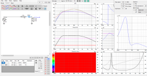
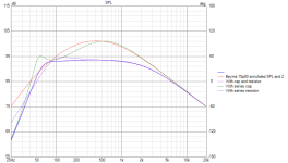
ps. it's simulated response and impedance of the Beyma 15p80, from example above.
- the boost on the above examples is mostly below the impedance peak frequency
- Also, as the cap increases high pass slope, which partly reduces excursion on the very lows, so perhaps distortion penalty isn't as bad as it could.
- peculiar thing with also a resistor added, straightens the response (reducing current on mids than at the resonance), and while the cap doesn't add that much boost anymore it still does some contouring of the Q, but not a boost anymore. Also distortion would be reduced some (hint of current drive).


ps. it's simulated response and impedance of the Beyma 15p80, from example above.
Last edited:
Someone who is building an active DSP system asked me about including the Passive Bass Boost in his design.
I replied:
When you are doing an active DSP system there is no reason to use the Passive Bass Boost. That is only for 100% passive systems. (Actually you should post this question on the group forum because other people need to know this):
-The large inductors will have hysteresis distortion, and the capacitors have Equivalent Series Resistance
-The Passive Bass Boost only gives a very limited amount of boost and it will only work within a certain range of frequencies just above resonance for any woofer
-DSP is far more powerful, and gives you the ability to shape the response however you want.
So you should put as few passive components in your system as possible. Like capacitors to protect the tweeters from DC for example.
I do think you should roll off the DSP below the cutoff frequency of the system so you don't overload your woofers.
stumbled Appon this today speed reading it wondered is this the same idea as you describe here ? https://www.aes.org/images/e-lib/thumbnails/1/5/15513_full.png
- Home
- Loudspeakers
- Multi-Way
- Open Baffle Bass Boost: +4 to +7dB w/ Passive Xover, No DSP