The noise floor for the AP2722 is about 6 to 8nV/RtHz. The Jung SR using an AD797 has noise of ~4nV/Rt Hz so you need an amplifier with a sub 1nV/RtHz noise floor to accurately measure regulator noise. The setup WJ showed in the 1995 articles still works.
When I get P3 boards will measure, but my experience with the P2 is that there is essentially NO difference in the P2 phono-pre output noise when powered by LM type regulators OR the Jung or Salas regs (set to the appropriate level, in the case of P2, +/-24V). Zen Mod is certainly correct.
When I get P3 boards will measure, but my experience with the P2 is that there is essentially NO difference in the P2 phono-pre output noise when powered by LM type regulators OR the Jung or Salas regs (set to the appropriate level, in the case of P2, +/-24V). Zen Mod is certainly correct.
so you need an amplifier with a sub 1nV/RtHz noise floor to accurately measure regulator noise
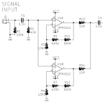
Here's a less expensive ($6.40 @ qty=1) way to proceed -- assuming very low source impedance as in a PSU.
First stage gain = 30dB, subsequent stages aren't noise constrained so select for high-GBWP and low price.
_
Attachments
Got on here to research finally building my Pearl 2 and see there is now a Pearl 3. I purchased boards and JFETS a while back and was just getting around to starting a winter project. Are all parts still available for the Pearl 2. I see a lot of needed components on back order. Also would the PSU be swappable If I built a Pearl 3 later.
@maxellfullmon
Pearl 2 is still fantastic phonostage, so yes, building it is a great plan!
Yes, you could use the 2 psu with 3.
What parts are backordered? If you have the Jfets, everything else on the Pearl 2 has ready substitutes, so completing it will be straightforward. Please continue your Pearl 2 questions in this thread - https://www.diyaudio.com/community/threads/building-a-pearl-2.204336/ we will be very happy to help.
The Device Under Test is not only the Regulator. The regulator is not the only offender. The raw DC power supply looks to be a worse offender. The jfets and 47K input resistor contribute additional noise.
Power line ripple can clearly be worse, a couple of inline CR filters help the LM regulators do their job.
I am looking at the input stage of the P3 including filters and regulator as the DUT.
For additional insight see this TI document.
https://www.ti.com/lit/pdf/tidu016?keyMatch=NOISE MEASUREMENT POST-AMP
Thanks DT
I used SSM2019 for the article, those I have were 1.0nV/RtHz or better, and it's differential so easy to use shielded twisted pair. It's about $6.00 in single quantities and available as DIP. Rather high input bias current, however!Here's a less expensive ($6.40 @ qty=1) way to proceed -- assuming very low source impedance as in a PSU.
Now use one of Gerhard's designs (of which he has a dozen at least!).
Sell a set to meHi. Still two sets of Pearl 3 PCB and and UDP3 power supply to sell. If interested let me know. I won't probably re-order more. So this is your chance...
Thanks
SB
send me a PM please
A question on power umbilical design for those building a Pearl 3.
The umbilical I'm using is a 3-pin XLR bought off of amazon. What was not clear to me at the time that I bought it is that XLR pin 1 is not a separate conductor like pin 2 and 2 are. Pin 1 is tied to the cable shield. I wired it as circuit ground, and I think this is a mistake based on comments I've read elsewhere. Circuit ground should be it's own separate conductor. Is this correct?
My current belief is that the umbilical shield should not carry currents other than whatever is induced in it and linked chassis from stray EMF. Is this correct? The umbilical shield should be tied to chassis ground, at least on the side of the power supply if I've read correctly. I am unclear if it should be tied to chassis ground on both the power supply side and the Pearl 3 side. What do people recommend?
I'm dealing with a potentially difficult situation as the mains supply to my stereo system has a floating ground, which I think makes shunting stray EMF to earth ground won't work. I have to solve it internally.
I sent you a PMHi. Still two sets of Pearl 3 PCB and and UDP3 power supply to sell. If interested let me know. I won't probably re-order more. So this is your chance...
Thanks
SB
Best,
Tony Z
PM sentHi. Still two sets of Pearl 3 PCB and and UDP3 power supply to sell. If interested let me know. I won't probably re-order more. So this is your chance...
Thanks
SB
So, I'm getting a little bit of noise on the right channel... I can only hear it when the preamp is at unity gain... and I stand within four feet of the speakers
The noise is sort of a "prrrfttt prft........... prrfftttttt...................' and so on. It doesn't seem to affect the quality of the sound.
I've verified it's not caused by the preamp or amp... or the cables.. or the cartridge. My prototype build has it all in one chassis. Jim had some noise in his test one chassis but he said the noise is different. My P3 has sockets for the op amps so I can roll them... I haven't tried rolling them yet.
Any one else having such noise in their P3?
@ranshdow
Hello Randy,
my wiring from the PSU to the amp (PEARL 3) is a 4 wire + shielding. I use 4-pole XLR-connectors. The shielding is only connected to one side (PSU - earthgound at IEC-inlet / case) - it does nothing else than shielding the 4 wires inside.
I use wire 1: +15V DC
wire 2: GND (audioground)
wire 3: PE or earthground (from PSU-earthground to case of PEARL 3)
wire 4: - 15V DC
My PSU is not yet in the case. I also have a very slightly hum (pretty sure 50 Hz from the mains).
Check also your connection from the vinylplayer - ground to ground of the PEARL 3. Where did you connect it to? To earthground of the PEARL3 or to
audioground?
Sometimes it can help to put a groundloopbreaker between audioground at PSU output to earthground - PSU (10 ohm resistor for example).
But this has to be tested...
Only some thoughts...
Cheers
Dirk
I have been reading about using the shield gnd at 1 end or both, if 1 end which, and there seem to be very strong cases to be made for each. One article, that seemed to make sense suggested that connecting both ends creates a "Faraday Cage". Wondering if others here would chime in?The shielding is only connected to one side (PSU - earthgound at IEC-inlet / case) - it does nothing else than shielding the 4 wires inside.
Dirk,
My crcrc board uses a diode bridge as a ground breaker on the PSU side.
TT ground should be to the ground post which is connected to the RIAA chassis and the ground point on the PCB highlighted in the build doc. This is audio ground.
Umbilical on RIAA box side should have connections for positive, audio ground, and negative.
Umbilical on PSU side can have the shield connected.
My build isn’t using an umbilical shield now. I’d have to do some reading and/or experimenting on shield connection to earth or audio ground.
You’re free to experiment with connecting shield on RIAA box. But note that this may bypass the ground breaker if you connect shield to earth ground on the PSU side.
Ciao Gianluca,🎅🎄🎁🎶 Santa Gianlu is comin' to town...🎅🎄🎁🎶
Is there the possibility to obtain the same faceplates in a standard Galaxy?
Buone Feste
- Home
- Amplifiers
- Pass Labs
- Pearl 3 Burning Amp 2023