IME, polymers datasheet declared leakage is for absolute worst possible case. Actual leakage values are usually two or three orders of magnitude lower. In example, Panasonic SEPC 100 uF/16V polymer with declared 320 uA leakage, at 7 V actually has less than 1 uA. That was confirmed with several voltage references for voltage regulators.According to this source the DC leakage of tantalum polymers, aluminium polymers and electrolytics are similar. The tantalum polymers I'm using have max DC leakage of about 50-70uA according to datasheets.
To my understanding, voltage regulators can’t suppress excess voltage applied to their output, only voltage drop caused by increased load. So, periodic voltage generated by X7R capacitor piezo effect at regulator output, will be corrected for negative part by regulator (regulator impedance applies here) but, for positive voltage above adjusted regulator output, it will rely on load to bring excess voltage down.Piezo effect creates a current, so the resulting voltage is proportional to node impedance. Suppose 33mOhm output impedance for the reg, and 33k resistor on VSET pin, that's a factor of 1 million worse for the cap on the VSET pin")
This is likely reason why some voltage references sound better with some load applied, as Markw4 mentioned.
That has been my experience as well but I don't have long time experience with them. Is it possible that leakage increases with component age?IME, polymers datasheet declared leakage is for absolute worst possible case. Actual leakage values are usually two or three orders of magnitude lower. In example, Panasonic SEPC 100 uF/16V polymer with declared 320 uA leakage, at 7 V actually has less than 1 uA. That was confirmed with several voltage references for voltage regulators.
Could be. I have those Panasonic capacitors in service for only one year and there is no change, as it shouldn’t be.That has been my experience as well but I don't have long time experience with them. Is it possible that leakage increases with component age?
However, we have at disposal new hybrid polymer capacitors with ESR as solid polymers, but declared leakage as good electrolytics.
https://industrial.panasonic.com/ww/products/pt/hybrid-aluminum
I tried various output caps for my custom AK4499 dac discrete Vref regulator. Differences were audible. It was possible to add enough capacitance such that output capacitors dominated transient response and limited regulator feedback loop bandwidth. In that case different caps types sounded different. The ones I liked best when the regulator was dominated by output capacitor sound were Rel Polystyrene in values of a few uf. However, it wasn't enough capacitance to do justice to bass sounds. Higher frequency sounds were very good quality. Probably the worst sounding caps were polymer electrolytics. They sounded to me like they produced some, yes, I'm going to say it, some signal-correlated noise. Ugly sound. That said Rohm BD34301EKV Evaluation Board Vref uses some small can size non-polymer aluminum electrolytics in parallel with some smaller caps located very near the dac chip that sound not too bad after some burn-in. The BOM says they are Nippon Chemi-con EMAR160ADA101MH63G. https://www.wclbuy.com/resource/attachment/lb_book/201611/9948dd3b8611c166053d78686a4a16dc.pdf
The smaller caps are listed as Murata GRM21BB11H104KA01L: https://static6.arrow.com/aropdfcon...f1b1c0b639a409e43151954/grm21bb11h104ka01.pdf
Vref is 5vdc.
Not sure if something might else have worked better, never got around to trying it.
The smaller caps are listed as Murata GRM21BB11H104KA01L: https://static6.arrow.com/aropdfcon...f1b1c0b639a409e43151954/grm21bb11h104ka01.pdf
Vref is 5vdc.
Not sure if something might else have worked better, never got around to trying it.
Last edited:
Did you take any measurements that you can share?I tried various output caps
One might expect someone just out of the sin bin to have learned something about trolling occasionally having consequences.
OTOH if serious people want to discuss listening tests and or the value of FFT measurements in various situations, I will be happy to oblige by PM or other troll-resistant means.
OTOH if serious people want to discuss listening tests and or the value of FFT measurements in various situations, I will be happy to oblige by PM or other troll-resistant means.
Normally I would not expect to hear much difference between reasonably implemented AK449x DACs. However having seen pictures of Markw4's DAC implementations I will have to make an exception to the rule.
Ouch! Does it look like a mess?
It looks like an AKM Evaluation Board, with another board underneath it where its details can't be seen. Interconnections between the two boards can't be seen. There are some power supplies off to the side. It sits inside a large steel case for shielding purposes. If you think AKM makes messy evaluation boards, you should probably complain to them not me.
It was a serious question. I've read about caps affecting the output. Since it was brought up publicly, share it with the public so that they can learn.OTOH if serious people want to discuss listening tests and or the value of FFT measurements in various situations, I will be happy to oblige by PM or other troll-resistant means.
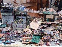
I'm tempted but let's keep it civilizedOuch! Does it look like a mess?
I have no experience with polymer electrolytics and I used to avoid tantalum capacitors for non-technical reasons, but ordinary aluminium electrolytic capacitors that haven't been used for a while usually start with a high leakage that gradually decreases to many decades below the specified value (which usually applies after two minutes).
Supercapacitors behave similarly, but their leakage decreases much slower (which is probably why their leakage spec typically applies after three days) and the leakage almost gets back to the old, high value when you discharge them and charge them again.
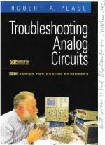
In fact there is an old Bob Pease article in which he shows that film capacitor leakage also slowly decreases to a value way below spec. He explains that the initial leakage is really dielectric absorption.
Supercapacitors behave similarly, but their leakage decreases much slower (which is probably why their leakage spec typically applies after three days) and the leakage almost gets back to the old, high value when you discharge them and charge them again.
In fact there is an old Bob Pease article in which he shows that film capacitor leakage also slowly decreases to a value way below spec. He explains that the initial leakage is really dielectric absorption.
...film capacitor leakage also slowly decreases to a value way below spec. He explains that the initial leakage is really dielectric absorption.
Their sound may change as that initial DA equilibrium settles for particular operating conditions (DC + AC). IME it can take two weeks for some polypropylene caps. Reversing the cap DC polarization can restart some of the settling effect. FFT shows pretty much nothing since DA produces a linear distortion, not HD (IMHO because of RC ladder network smearing of time-domain transients, aka linear waveshaping).
Last edited:
Haven't done much real research or experimental work, have you guys?Ouch! Does it look like a mess?
After decades in a major research lab, one knows better than to make such silly comments.
Perhaps some work by RAP will illustrate the point. Surely you must know who he was?
Attachments
Yeah, if the load is drawing current, then the regulator behaves like a single-ended class A amplifier. Its output impedance applies to both current polarities. Whatever current is sourced by the capacitor will result in the regulator sourcing less current by the same amount, with the load not seeing any difference.To my understanding, voltage regulators can’t suppress excess voltage applied to their output, only voltage drop caused by increased load. So, periodic voltage generated by X7R capacitor piezo effect at regulator output, will be corrected for negative part by regulator (regulator impedance applies here) but, for positive voltage above adjusted regulator output, it will rely on load to bring excess voltage down.
This is likely reason why some voltage references sound better with some load applied, as Markw4 mentioned.
If there is no load though, then the regulator can only source current, and things can happen.
For example the output noise spectrum of ADP151 is completely different with and without load. This is most likely the case for most LDOs, as the transconductance of the pass transistor depends on current. That influences the whole feedback loop of the regulator.
I tried various output caps for my custom AK4499 dac discrete Vref regulator. Differences were audible.
As usual, I will ask the annoying question:
What kind of current does AK4499 draw on the reference?
Also I remember the layout on this board being terrible. If the reference chip has its ground pin far away from the DAC, it will produce a voltage relative to the reference chip's ground. If this is not the same as the DAC ground due to bad layout, then putting a big cap next to the DAC to tie VREF to the DAC's ground can reduce the noise on VREF... but it is better to not screw up the layout in the first place, of course...
What kind of current does AK4499 draw on the reference?
In my case it draws 22mA per channel. However, there are also some 100R regulator output load resistors used with my discrete Vref regulator. My regulator board is (for now) mounted over the dac chip with a double-layer electrostatic shield between the two. Leads from the regulator board to the dac chip and ground are roughly 3cm long. And, yes, the length does make a difference. As ESS suggested for their dacs, the Vref (AVCC) regulator should be very close to the dac chip. Vref bypass caps even closer.
Haven't done much real research or experimental work, have you guys?
My thoughts exactly.
Considering what was discussed earlier in this thread regarding the criticality of Vref I find this hilarious. But I'm sure it has good sound.My regulator board is (for now) mounted over the dac chip with a double-layer electrostatic shield between the two. Leads from the regulator board to the dac chip and ground are roughly 3cm long. And, yes, the length does make a difference. As ESS suggested for their dacs, the Vref (AVCC) regulator should be very close to the dac chip. Vref bypass caps even closer.
- Home
- Source & Line
- Digital Line Level
- Phase noise in DS dacs