The stories are helpful and entertaining, thanks.
(You were referring to surround resonance here.) Can added mass sufficiently perturb and identify the existence of this or would you suggest another method?
You can easily isolate which blip equates to which part.
(You were referring to surround resonance here.) Can added mass sufficiently perturb and identify the existence of this or would you suggest another method?
This is what I've found too, particularly when tweaking 8" full range drivers.A point on woofer peaks. Although most people assume that HF woofer peaks must come from the woofer center, most modal analysis shows that strong upper modes come from activity around the woofer cone's perimeter.
Would you say that it's caused predominately by bell mode resonances, or radial bending modes ? Or is it both ?
By far the most successful mod I've found to smooth cone breakup in the upper midrange (at least on the Coral drivers) is to add a pattern of small adhesive foam blocks within the outer 25mm section of the cone. (Something I've been doing since about 2002)
It doesn't take much either - on this 8" driver each block is about 9mm wide by 20mm long by 3mm thick. Eight are placed on the rear of the cone equally spaced around the perimeter parallel to but not touching the surround (about 3mm clearance from the cone edge, as it's a reverse roll surround) with a further 4 strips about 15mm from the edge, spaced in between the other strips. (So that if you trace a line from the centre to the edge, no two strips are in line)
I don't add any strips further than 25mm in from the edge of the cone, nor do I add any to the whizzer cone, or make any attempt to damp the surround, none of which seem to be necessary, at least on this driver.
By changing the number and exact position of strips (including slightly staggering their radial distance from the centre) the response in the 3-5Khz range can be dramatically improved and optimized.
Not only does the driver measure a lot flatter from 3-5Khz with the carefully placed damping, (and measure much better on a CSD) more importantly to my ear it also almost entirely eliminates what I refer to as "random cone breakup hash/noise".
I'm not sure how to describe this noise exactly, or by what name other people call it, but to me it sounds like a broad band random noise spectrum with a long decay which occurs throughout the cone breakup region of a driver when stimulated anywhere in that frequency range, but doesn't sound like a single frequency High Q resonance which you hear more as a tone.
Most paper cone woofers exhibit this characteristic sound in their breakup region if you listen to them unfiltered. Normally in a good multi-way design the network would put this region well into the stop band, but with a full range driver you have nowhere to hide it, so damping the cone is the only option.
The reason why I ask whether it's bell modes or radial bending modes is that I had originally assumed years ago that it's the radial modes that are being damped (especially when the distance from the centre to the damping strip controls the frequency where damping is most effective - about 3Khz right at the edge of a 8" cone, and about 4Khz 25mm in from the edge) but it occurs to me more recently that it may in fact be primarily bell modes.
Because the strips are 20mm x 9mm and parallel to the edge of the cone, bell modes traveling around the cone should flex the strips (and thus dissipate energy) more than bending waves traveling from centre out to the edge. I've tried the strips at right angles to the edge of the cone instead of parallel and it doesn't work - it has some effect on the response but not a desirable one.
Another thing that points towards bell modes is it seems the number of individual foam strips around the perimeter is more important than the total strip area - 8 strips works well, 4 doesn't, even if they're each twice as long. This suggests to me that maybe the right number of individually spaced strips is disrupting the formation of bell modes.
The foam strips are so effective I'm surprised that commercial paper cone drivers don't seem to build something like that into the design. Obviously manually applying individual sticky foam blocks to a cone is not a viable manufacturing technique, but it shouldn't be too hard to have a circular adhesive foam "mask" which is mostly cutouts with only the pieces where blocks are wanted left, along with tiny joining sections. A big grid covering the outer 25mm of the cone, consisting mostly of holes, which can then easily be lined up and pressed onto the back of the cone before the cone goes into the frame. By simply altering the pattern of cutouts and the thickness of the foam the optimum damping characteristic for a given cone could be obtained and then easily and accurately mass produced.
Last edited:
This is what I've found too, particularly when tweaking 8" full range drivers.
Would you say that it's caused predominately by bell mode resonances, or radial bending modes ? Or is it both ?
I'll have to drag out some of my references on cone modal analysis, but from what I remember the bell modes happen at the lowest frequencies (are first to occur when moving up the scale) and tend to have little acoustical contribution. It sounds like you are working on the radial bending modes.
If we think of a cone as an unterminated transmission line, then your perimeter damping scheme sounds like it provides better termination. DLR was showing very useful results for his treatment of "wet look" at the surround. They sound similar in effect. Do you have some before and after curves?
David S.
That's what I originally thought. The cones already have 3 stiffening ribs around the perimeter which are presumably there to help brace the cone against bell modes, although how effective they are in practice I don't know.I'll have to drag out some of my references on cone modal analysis, but from what I remember the bell modes happen at the lowest frequencies (are first to occur when moving up the scale) and tend to have little acoustical contribution. It sounds like you are working on the radial bending modes.
A transmission line is exactly how I like to think about the cone of a wide band driver like this. (Or any driver beyond the piston range for that matter)If we think of a cone as an unterminated transmission line, then your perimeter damping scheme sounds like it provides better termination.
However people generally talk about trying to terminate the bending waves just at the edge, and with realistic surround materials I don't think you can ever get a close enough impedance match to have much effect on the standing waves - a surround is just too different to a cone, and too narrow in width as well. Damped surrounds do improve the surround dip at ~1Khz but I'm not sure that it does a lot for the higher modes in the 3-5Khz range.
You can make the cone itself a lot more lossy throughout (polypropylene etc) and get a smoother response, but you'll also kill the high frequency response as the higher frequency bending waves are absorbed well before the wave reaches the edge. It's like trying to wade quickly through water...
A really interesting article I read years ago was on the development of the FST kevlar midrange unit in the B&W Nautilus series, where rather than trying to eliminate the standing waves on the cone they harnessed them. The particular fabric weave they used meant that although the cone was circular, the propagation speed in different directions was different, such that acoustically the cone is square.
Because of that standing waves don't form symmetrically right around the radius of the cone, and there are no spot frequency resonances where the effective path length from centre to edge is equal all the way around. Better still, at any given frequency above breakup adjacent sectors of the outer section of the cone are out of phase with each other cancelling their radiation leaving only the centre of the cone active, thus improving dispersion by reducing effective cone area.
(I hope I'm getting this right, it's years since I read the white paper)
Around the same time I thought about adding discrete damping strips near but not at the edge of a conventional cone, and staggering the distance of alternative strips (from the centre) so that as well as providing some resistive damping to the standing waves, would by their being offset in from the edge of the cone alter the pattern of standing waves in adjacent sectors of the cone, and effectively make the cone non-circular for standing waves, much like the B&W driver. Different angular sectors of the cone have different standing wave patterns occurring at different frequencies instead of them all occurring at the same frequencies, which usually happens in a circular homogeneous cone.
That was my theory anyway, I don't have the measurement systems (laser etc) to see what's really going on, I can only measure the frequency response and listen to the results, but it seems to work quite well.
I do, not very accurate ones though, as my measurement environment and equipment at the time was quite limited.DLR was showing very useful results for his treatment of "wet look" at the surround. They sound similar in effect.
Do you have some before and after curves?
David S.
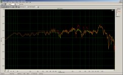
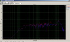
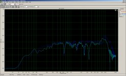
Image 1 is a before/after measurement taken around 2003 with SpectraLab so it's only a slow swept tone measurement, with no gating and is full of room reflections etc. It was also taken with the speaker in it's normal playback position in the room, relatively near walls, mic at about 1 metre.
Red is before, Yellow is after the strips were added. I was very careful that nothing was moved or changed between the two - the driver was unscrewed from the front of the cabinet and taken away to have the strips added, with cabinet, microphone, and measurement system all being left exactly as is, so although the absolute accuracy is poor due to reflections (and uncalibrated mic) the relative change is pretty accurate.
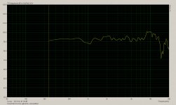
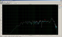
I think the change from 2.5Khz to 5Khz speaks for itself really. The notch at 3.5Khz present both before and after I think in hindsight is a microphone stand reflection, not a real notch in the driver - Image 2 is the same driver measured on the same baffle (but in a different room) 8 years later with ARTA using a 4.2ms gate time and a bit more care and attention to avoiding mic clamp reflections, and the 3.5Khz notch is nowhere to be seen. (I'm not 100% sure if I used the same microphone for the older measurements either - it was around the time I switched mics)
Below 2Khz there is about a 1 dB loss in overall sensitivity due to the approximately 1 gram added mass from the foam strips. In the treble there's no real change in sensitivity since no mass was added to the whizzer cone which along with the dome is dominating the response by about 7Khz.
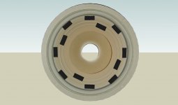
I don't have any good photos of the strip layout, no, because they're largely obscured by the frame of the driver, so a picture from one angle would only ever show a couple of the strips. What I do have though is a Google Sketchup model of the driver I made a while back, so I've hidden the magnet, frame, etc and placed strips on it which give a good idea of their location and proportions.Interesting...do you have some pictures ?
Image 3 is looking at the rear of the cone straight on, don't be confused by what looks like a whizzer cone in the middle, it really is the back of the cone, it's just that I used the same texture image to model the front and rear of the cone, as you don't normally see the middle of the rear of the cone in the completed model with magnet/frame/spider etc in place

Attachments
Last edited:
Hi Simon,
Your figure 1 looks like a very useful improvement in the 2 to 5kHz range. Interesting that there was minimal effect above.
I'd spent many hours in years past playing with doping compunds, cutting slots, etc. The only problem is trying not to do permanent damage on a path that doesn't pan out.
Inherently deader cone material is an interesting avenue also. I worked for a company early on, that was too cheap to put inductors in crossover networks. I found a 10" cone made of something so soft that is seemed like blotter paper. Rolled of on its own around 700. The interesting thing was that it sounded cleaner: it couldn't radiate harmonic distortion! (A real difference between electrical and mechanical rolloff.)
All good stuff probably worthy of its own thread: "Driver mods with measurements".
David S.
I think that the lack of much effect above 5Khz is due to the driver being dual cone.Hi Simon,
Your figure 1 looks like a very useful improvement in the 2 to 5kHz range. Interesting that there was minimal effect above.
The main cone by itself (as measured on another de-whizzered unit) rolls off above about 6-7Khz.
Also looking at the excess phase curve shows excess phase starting to appear just below 4Khz and reaching nearly 180 degrees at 10Khz - the half way point of this shift is around 6Khz, so I assume this means that the accoustic crossover point between the two cones is occurring around 6Khz, and is approximately 2nd order ?
In either case, the whizzer cone and dome are dominating the measured response above 6Khz, so even if the damping were improving the smoothness of the stop-band roll-off of the main cone it wouldn't show up significantly in the summed response. On a single cone driver I'd expect to see an improvement in the smoothness of roll-off with the damping strips in place.
Exactly my thoughts, and why I've resisted the urge to try permanent modifications on vintage drivers that are hard to replace, such as doping compounds on the cone or surround, removing dust caps, etc, and I thought that the adhesive foam strips could be an interesting way of tweaking the driver in a non-permanent, non-destructive way, I didn't really even know if it would work when I first tried it, but I thought I could always undo it later.I'd spent many hours in years past playing with doping compunds, cutting slots, etc. The only problem is trying not to do permanent damage on a path that doesn't pan out.
The only problem with that is that on these vintage drivers the paper is uncoated and extremely dry, so whilst you can peel the strips off carefully if they weren't pressed on too firmly and if you did so within a few days, once they've been on for a few months the adhesive leeches into the cone slightly bonding them very strongly and peeling them off will peel off a thin layer of the paper along with it...
Because I had the strips on and off several times over a few months trying slightly different arrangements before settling on the final one, the paper is now significantly thinner in spots... That plus the fact they've been on 8 years now means that I can't really remove them now without damaging the cones somewhat.
On the plus side, I was originally worried about the long term stability of an adhesive foam block - would it fall off or change it's properties over time ? Apparently not, as they're all still solidly attached with no apparent deterioration.
On a cone that is already coated with something, or somewhat smooth, the adhesive blocks will peel off without leaving a mark, it's only the very dry uncoated paper that's a problem.
Good point about the harmonic radiation - that can certainly be a problem with using a full range driver as a midrange driver with an electrical crossover, especially if there is a lift in its treble response. It shows up as increased 3rd order distortion products in the upper midrange, and an electrical filter can't do anything about it...Inherently deader cone material is an interesting avenue also. I worked for a company early on, that was too cheap to put inductors in crossover networks. I found a 10" cone made of something so soft that is seemed like blotter paper. Rolled of on its own around 700. The interesting thing was that it sounded cleaner: it couldn't radiate harmonic distortion! (A real difference between electrical and mechanical rolloff.)
I find it fascinating, and I think there is so much more that could yet be done to optimize wide band drivers by truly looking at them as transmission lines when designing them. A few have taken that approach (like B&W's FST) but most designers seem content with designing drivers for use only in their piston range.All good stuff probably worthy of its own thread: "Driver mods with measurements".
David S.
The problem with keeping a midrange driver strictly in its piston range is that it's inevitably going to be physically too small to have sufficient dynamic capability, or require crossing over to the tweeter far too low. (Introducing tweeter IM etc)
I really do think designing moderately large (~8") midrange drivers with full appreciation of transmission line theory to greatly extend their high frequency extension and smoothness at the top end is the way forward.
I just wish I had more time and resources to experiment further.
Last edited:
Thanks for the datas and comments, I think I will give it a try and maybe I will not be the only one.
Bear in mind, what works well for driver A might not make much difference on driver B, and may make driver C worse, all depending on the size of the cone, cone material, pre-existing internal damping, and so on. There's no magic pattern that would benefit all drivers, and I spent a LOT of time on trial and error to find what worked for these specific drivers.
I've used this mod on half a dozen different drivers, but all were 8" full range paper cone, it might not be effective on other cone materials or cone sizes. Each different model of driver I tried needed a somewhat different placement of blocks to get the flattest response, and some drivers I tried (FE207E) didn't really seem to benefit much at all.
I would make some general comments though:
(1) Adding damping patterns like this only has an effect above the piston range of the driver. Below that frequency (somewhere around 1-2Khz on this driver) all that happens is a loss of sensitivity and increase in Mms/Qms regardless of pattern due to the total added mass.
(2) Measurement is critical. If you can't measure the before and after response fairly accurately and consistently, you're just stabbing in the dark. The wrong pattern can make cone resonances and frequency response flatness much worse.
(3) The closer to the edge of the cone, the lower the frequency affected. On an 8" paper cone the edge seems to correspond to about 3Khz. The 4 further to the centre strips on my diagram correspond to about 4Khz. On a larger cone the edge would correspond to a lower frequency while the edge of a smaller cone would correspond to a higher frequency.
If there is a big peak at a certain frequency you can target it by adjusting the distance of the strips from the centre, but I wouldn't recommend going any further than about 1/4 of the way in from the edge of the cone, as most of the breakup occurs near the edge. Further in seems to make things worse or have little effect.
(4) Staggering the strips so they're not all at the same distance from the centre seems to be important, as does leaving some gaps. I presume this is because the gap allows the standing wave for that sector to form over the full length of the cone + surround, and counts as if a strip were placed right at the edge of the frame. (Thus there are 3 different distances in my example)
(5) Although you want to stagger the distances so not all strips are the same distance from the centre, it's important for the pattern to be radially symmetric. You'll notice that my pattern can be divided up into four identical quadrants with the entire pattern being symmetric.
(6) Too much damping is a bad thing. If the strips are too long or too thick they may over damp certain frequencies and put dips in the response. If so use thinner strips or make them a little bit shorter. The less the added mass to get the desired response the better.
(7) Try to measure CSD as well as frequency response. Whilst in general adjusting the damping configuration to get a flatter frequency response improves the CSD, this is not universally the case, especially on a dual cone driver, which is never minimum phase at high frequencies.
Sometimes striving to eliminate a particular peak can actually worsen the CSD. I'm not sure why this is, except that you may be inadvertently trying to cancel one resonance by introducing another one on a different part of the cone. Given a choice between flatter frequency response and worse CSD, or cleaner CSD and slightly more lumpy frequency response, I think the latter sounds better.
The cause of peaks and dips on a frequency response graph can sometimes be ambiguous, (resonant vs non-resonant) especially on a large driver operating at high frequencies relative to the cone size, but the time domain view given by the CSD always shows the truth about resonances, and should be believed over the frequency response if there is any disagreement between the two.
Last edited:
This was my experience as well, though it was totally counter-intuitive. My thought was that it might "unbalance" the cone and introduce some rocking into the cone due to odd mass distribution.(5) Although you want to stagger the distances so not all strips are the same distance from the centre, it's important for the pattern to be radially symmetric. You'll notice that my pattern can be divided up into four identical quadrants with the entire pattern being symmetric.
A three part arrangement initially seemed like the optimal location. The surprising thing was that no test of three points improved it without additional, more detrimental changes. Only later did I try just two.
At some point I recalled seeing the two "ears" on some Accuton drivers, so I focused on two only for any fixed distance from the former. The result was that just a very few of these pairs largely eliminated most of the higher frequency resonances.
Dave
One reason I opted for a symmetric layout - in theory the centre of mass of the cone should still be along the same axis, as every strip has an equal and opposite which is 180 degrees away on the far side of the cone and at the same distance from the centre. It also seems to work best from the point of view of damping the resonances.This was my experience as well, though it was totally counter-intuitive. My thought was that it might "unbalance" the cone and introduce some rocking into the cone due to odd mass distribution.
So if I understand you right, you mean that initially you were using groups of 3 dots which were 120 degrees apart and the same distance from the centre ? And then another group of 3 dots at some other offset from the centre and with some angular offset from the first group ?A three part arrangement initially seemed like the optimal location. The surprising thing was that no test of three points improved it without additional, more detrimental changes. Only later did I try just two.
Interesting that groups of 3 (per equal distance) didn't work without causing more problems than they fixed - I didn't try 3, but I did try 2, 4, and 8.At some point I recalled seeing the two "ears" on some Accuton drivers, so I focused on two only for any fixed distance from the former. The result was that just a very few of these pairs largely eliminated most of the higher frequency resonances.
I first started off with 4 strips at 90 degree intervals near the edge of the cone (top/bottom/sides in the diagram) and there was significant improvement but it wasn't enough. I then added another 4 strips in between them at 45 degree intervals, making a total of 8, and this made a big improvement, especially around 3Khz, however it still left quite a big peak at 4Khz.
I then tried adding 2 strips further in opposite each other, then later 4 strips as shown in the diagram, which pulled down the peak at 4Khz a lot. (There is still about a 2dB peak there which I equalize in the network, along with the broad 3dB peak at 2Khz)
(On another pair of similar but different drivers, I only added the 8 strips around the perimeter and found I didn't need the extra 4 further in, and that all they did was put an unwanted dip in the response)
The interesting thing is that I found pairs of 2 strips didn't work very well for me. When going from only the 8 strips around the edge to adding 2 inner strips it reduced the resonance at 4Khz somewhat but it actually added a new low level resonance at another frequency nearby. I forget if it was higher or lower, but despite its low amplitude the newly added resonance had a very long decay time of several ms. It wasn't really noticeable on the frequency response plot, only on a CSD as a low level but long lasting ridge. I think I could just hear it too, on certain music.
Adding 2 more strips to make it a group of 4 spaced at 90 degrees eliminated the spurious new resonance, as well as further reducing the original 4Khz resonance. Staggering 2 of the opposite strips further in by half a block width improved the response at 4Khz slightly more, but if I staggered them any more than that (such as a full block width) the spuriously added low level resonance would return.
It seems that there must be at least 4 blocks equally spaced around the circumference at any given radius where there is a block, although I'm baffled as to why. This is what got me wondering about whether there is a secondary effect going on which is affecting bell modes - maybe the spurious low level resonance is a bell mode, and only adding damping/mass at two 180 degree intervals stimulates (or allows) a particular bell mode, while adding damping/mass at 90 degree intervals (or less) suppresses the same mode.
Whatever the reason was, 4 or 8 strips per radius seems to work well, 2 didn't for me. I'm unsure how 12 or 16 strips per radius might perform on a larger driver, I'll have to try it one day on a 12" woofer.
Last edited:
I am not up on all the technical reasons things work or they don't but I have used alot of highend speakers PSB Platinum, Dynaudio, Triad....looking for certianly sound and output. I finally built a set with drivers from John at Acoustic Elegance and can tell you they are nothing short if amazing absolutly no noise from phase plugs or any measurable responce not supose to be there. He had tested several other mids for me and the dust cap breakup was so bad he went as far to change them out to different materials sizes shapes and dampenings added which all did help but as he explained just moved it around somewhere else in the frequency range all till he broke down and built a set of custom drivers to eliminate it and used a phase plug. Now his TD6
Sorry coming from someone who doesn't know why but it just works. I do agree there are some phenomenal sounding speakers that use a dust cap but could they sound better with a phase plug designed right?
Sorry coming from someone who doesn't know why but it just works. I do agree there are some phenomenal sounding speakers that use a dust cap but could they sound better with a phase plug designed right?
While looking through old measurements I've found some more damping experiments measurements on two different drivers that may be of interest. (Apologies to those only interested in phase plug discussion for derailing the thread again, although I have some on-topic phase plug measurements I can post later as wellHi Simon,
Your figure 1 looks like a very useful improvement in the 2 to 5kHz range. Interesting that there was minimal effect above.
I'd spent many hours in years past playing with doping compunds, cutting slots, etc. The only problem is trying not to do permanent damage on a path that doesn't pan out.
)What's interesting about these measurements is that they're from two different yet similar models of driver - to the eye they look like a very similar if not identical design (8" paper dual cone) yet they measure very differently indeed, showing how the largely invisible to the eye materials properties and composition is just as important if not more important than the actual physical geometry of the design.
For reference the driver I posted response graphs of previously was a Coral Flat 8 II. (The driver in my signature pic)
The ones I'll post in this message are the Coral Flat 8A. Visually they look like the same driver, but there are some differences - in the particular pair I have, they have very stiff surrounds, probably suffering from stiff surround syndrome with age. (They're close to 40 years old now)
Supposedly a fabric surround but it's so stiff that it's either heavily doped with resin or varnish that has gone hard over time or it's some other material, maybe even phenolic. The Fs is 105Hz because they're so stiff.
On the other hand the Flat 8 II surrounds are extremely soft and supple fabric, (probably porous too, as they don't seem to be doped with anything) so soft that for the same cone mass the Fs is around 38Hz.
An additional difference is that I (very stupidly, in hindsight) coated both cones with a couple of thin layers of a water based rubber and carbon compound. (Otherwise known as the stuff that you coat tyres with....) This had surprisingly little effect on the main cone, but a rather unfortunate effect on the whizzer cone. Unfortunately I don't have a directly comparable before and after measurement for this change, so the baseline measurement I'm providing is after this coating but before adding foam strips.
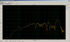
Given all that, the first response shows the "unmodified" (before foam strips but after ill-advised coating) response of the driver in red - which looks almost nothing like the zig zag response of the previous driver. There is however a dip around 3.2Khz and a large peak at 3.8Khz on the order of 6dB, which is a classic cone breakup resonance, albeit quite a lot better controlled than the other driver.
From what I can remember, the coating I applied made very little difference to this part of the response, so I can only assume that either the paper internal composition is a bit different, or the rather hard, stiff surround is better terminating the edge of the cone at high frequencies.
In any case I wanted to try to smooth out that spike at 3.8Khz, so I experimented with foam strips. I have 3 different combinations which I kept measurements for and I think they're interesting in showing just how much the response can be tailored by the number and position in strips, and the iterative approach I took.
The yellow response in image 1 was my first attempt - consisting of 4 strips at 90 degrees right near the edge of the cone and another 4 in between them spaced in about 20mm from the edge. The big spike is clearly tamed down and the dip at 3.2Khz improved slightly, but I thought I could do better than this.
Configuration 2 in dark blue in image two was achieved by doubling the number of strips but keeping the same basic layout - so now there are 8 equally spaced strips at the edge, and 8 equally spaced strips in between these and offset in by about 20mm. This pulls the response down even further, with the response at 4Khz where we want it but now we have a bit of a hole around 3.2Khz.
4Khz corresponds to the inner strips while 3.2Khz corresponds to the outer strips so I tried removing every alternate outer strip - leaving 8 inner strips and 4 outer strips. The result is the light blue response in image 3. This is flat within +/- 2dB from 2.7Khz to 6Khz, quite an achievement for an 8" whizzer cone driver IMHO, especially compared to the original red response. The droop from 7-8Khz and the peak from 9-12Khz are both due to the aluminium dust cap resonance and its interaction with the whizzer cone output.
What about the large dip at 2.5Khz ? None of the foam strip mods altered this in any way, and this notch is real, not some measurement artefact. Sadly, the cause of this notch is the coating I applied to the whizzer cone.
Although I don't have accurate and directly comparable measurements, I know for a fact that this large notch was not present before I coated the whizzer cone. BIG mistake.The fundamental mechanical resonance of the whizzer cone at ~2.2Khz which is normally fairly low Q, and in phase with the response of the main cone (well, at least less than 120 degrees) causing a modest bump in the response that can be corrected quite well with an RLC compensator or PEQ.
Somehow the coating has altered the cone properties to affect the phase shift and Q to the point where the whizzer cone and main cone are 180 degrees out of phase and almost equal in amplitude on one side of the resonance, so a notch appears.
Nothing I've done to try to undo this mistake has ever returned them to their original no-notch response, and there is nothing that can be done electrically to compensate for it either, so sadly those drivers were never used in a completed design, (and have become a bit of a driver tweaking testbed) because the resonance of that notch is actually quite audible and annoying.
So on this particular driver I think the foam damping strips were highly successful, but the overall response of the driver was ruined by the tampering with the whizzer cone. Pity. If I knew what I knew now I would never have touched the whizzer cone or applied any coatings - I would have gone straight to the foam strips.
In the next post I have another driver where foam strips whilst altering the response, didn't give a satisfactory final result. (Just to show that they can't work miracles on a really bad driver
)Attachments
This is yet another Coral driver - The Coral 8A-100. My Dad had a whole bunch of these and these were actually the first drivers I experimented with foam block damping on, because there were such obvious resonance problems with them to the point where even just touching the perimeter of the cone with your fingers made a big difference to the sound of the resonances, which is what got me thinking about sticking foam blocks on in the first place, and where to put them.
The one I show the measurements for was the worst one by far - most of the others measured considerably better in the treble, although all of them had the notch at 2.5Khz and peak at 3Khz, and all measured quite differently from each other.
Again physically they look much like the Flat 8, but from what I understand they were a "budget" model manufactured using the same moulds but not necessarily the same materials (or level of quality control...) and sold OEM without the Coral brand. (None of them have Coral written on them, only the model number)
They have a relatively soft fabric surround with a lot of travel like the Flat 8 II, but they're clearly doped with something. They also have a paper dust cap at the base of the whizzer cone rather than the vented aluminium dust cap of the other two models. The cones are jet black, compared to the pale cream colour of the other models, but otherwise appear to be the same geometry, including perimeter stiffening rings. Their sensitivity is about 2dB lower with a higher Qts and the magnet looks a bit cheaper.
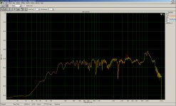
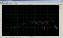
The unmodified response is in red in image 1. Yuck! That really is pretty bad, and it's no wonder that particular driver sounded so bad, in fact I would go so far as to say it's defective in some way, as the other 8A-100's whilst not exactly flat, were nowhere near that bad.
The difference between the peaks and dips is close to a staggering 35dB. Yellow in image 1 is more or less the same configuration of strips applied successfully to the Flat 8A in the previous post - you can clearly see a reduction in the peaks at 3Khz and 4Khz, and an improvement in the notch at 3.5Khz, but it's still pretty awful.
No combination that I tried would give significantly better results than this - it just moved the peaks and dips around in frequency. I then started to wonder if a whizzer cone resonance could be the problem, so I tried adding 4 foam strips behind the edge of the whizzer cone, the result is in cyan in image 2. There's a clear improvement from 4-7Khz, but there is still a big notch at 2.5Khz and 3.5Khz.
From this its pretty clear that there are serious cone breakup problems within the whizzer cone on this driver. (But not the others) From memory in this particular driver the whizzer cone was sticking out at least 5mm, maybe 10mm further from the main cone than all the other drivers, so it's possible that this shifts the resonances and relative phase shift of the two cones to the point where destructive interference becomes a problem.
Or it may be a difference in the materials composition - maybe the coating applied to make the cone black (it looks like its been spray painted matte black) has enough of an effect on the critical damping and stiffness to weight ratio of the whizzer to cause problems. (The cone is not nearly as "crisp" as on the better drivers - it feels a bit soft and soggy) Whatever it is, both cones have serious breakup problems that cause a rather ugly summed response which is full of destructive interference and resonances and makes for an essentially unusable driver.
Image 3 is comparing the best damped response I could get from the Flat 8A (dark blue) with the best damped response I could get from the 8A-100 (cyan) - even with all the tweaking its nowhere near as good, despite being largely the same design of driver. (The 650Hz and 1.6Khz notches are measurement environment reflection artefacts, but all the other notches really are in the drivers responses)
The one I show the measurements for was the worst one by far - most of the others measured considerably better in the treble, although all of them had the notch at 2.5Khz and peak at 3Khz, and all measured quite differently from each other.
Again physically they look much like the Flat 8, but from what I understand they were a "budget" model manufactured using the same moulds but not necessarily the same materials (or level of quality control...) and sold OEM without the Coral brand. (None of them have Coral written on them, only the model number)
They have a relatively soft fabric surround with a lot of travel like the Flat 8 II, but they're clearly doped with something. They also have a paper dust cap at the base of the whizzer cone rather than the vented aluminium dust cap of the other two models. The cones are jet black, compared to the pale cream colour of the other models, but otherwise appear to be the same geometry, including perimeter stiffening rings. Their sensitivity is about 2dB lower with a higher Qts and the magnet looks a bit cheaper.
The unmodified response is in red in image 1. Yuck! That really is pretty bad, and it's no wonder that particular driver sounded so bad, in fact I would go so far as to say it's defective in some way, as the other 8A-100's whilst not exactly flat, were nowhere near that bad.
The difference between the peaks and dips is close to a staggering 35dB. Yellow in image 1 is more or less the same configuration of strips applied successfully to the Flat 8A in the previous post - you can clearly see a reduction in the peaks at 3Khz and 4Khz, and an improvement in the notch at 3.5Khz, but it's still pretty awful.
No combination that I tried would give significantly better results than this - it just moved the peaks and dips around in frequency. I then started to wonder if a whizzer cone resonance could be the problem, so I tried adding 4 foam strips behind the edge of the whizzer cone, the result is in cyan in image 2. There's a clear improvement from 4-7Khz, but there is still a big notch at 2.5Khz and 3.5Khz.
From this its pretty clear that there are serious cone breakup problems within the whizzer cone on this driver. (But not the others) From memory in this particular driver the whizzer cone was sticking out at least 5mm, maybe 10mm further from the main cone than all the other drivers, so it's possible that this shifts the resonances and relative phase shift of the two cones to the point where destructive interference becomes a problem.
Or it may be a difference in the materials composition - maybe the coating applied to make the cone black (it looks like its been spray painted matte black) has enough of an effect on the critical damping and stiffness to weight ratio of the whizzer to cause problems. (The cone is not nearly as "crisp" as on the better drivers - it feels a bit soft and soggy) Whatever it is, both cones have serious breakup problems that cause a rather ugly summed response which is full of destructive interference and resonances and makes for an essentially unusable driver.
Image 3 is comparing the best damped response I could get from the Flat 8A (dark blue) with the best damped response I could get from the 8A-100 (cyan) - even with all the tweaking its nowhere near as good, despite being largely the same design of driver. (The 650Hz and 1.6Khz notches are measurement environment reflection artefacts, but all the other notches really are in the drivers responses)
Attachments
Last edited:
I've tracked down a link to the B&W Nautilus 801 design white paper that I was referring to which I first read about 7 years ago:A really interesting article I read years ago was on the development of the FST kevlar midrange unit in the B&W Nautilus series, where rather than trying to eliminate the standing waves on the cone they harnessed them. The particular fabric weave they used meant that although the cone was circular, the propagation speed in different directions was different, such that acoustically the cone is square.
Because of that standing waves don't form symmetrically right around the radius of the cone, and there are no spot frequency resonances where the effective path length from centre to edge is equal all the way around. Better still, at any given frequency above breakup adjacent sectors of the outer section of the cone are out of phase with each other cancelling their radiation leaving only the centre of the cone active, thus improving dispersion by reducing effective cone area.
(I hope I'm getting this right, it's years since I read the white paper)
Around the same time I thought about adding discrete damping strips near but not at the edge of a conventional cone, and staggering the distance of alternative strips (from the centre) so that as well as providing some resistive damping to the standing waves, would by their being offset in from the edge of the cone alter the pattern of standing waves in adjacent sectors of the cone, and effectively make the cone non-circular for standing waves, much like the B&W driver. Different angular sectors of the cone have different standing wave patterns occurring at different frequencies instead of them all occurring at the same frequencies, which usually happens in a circular homogeneous cone.
http://www.hifiportal.co.uk/Articles/Article0026-Development%20of%20the%20Nautilus%20801.pdf
Excellent reading material for anyone interested in the modal/resonant behaviour of cones and the interesting approach that B&W's engineers took to cleverly turn the modal behaviour of the cone into an advantage instead of trying to eliminate it.
Although it's very different to what I'm doing with my damping strips, they both (as far as I can see) have the effect of preventing the radial standing wave pattern from being identical around the entire rotation of the cone, thus producing different standing wave patterns in different "sectors" of the cone.
There is also a nice little video summary from an interview with Dr Peter Fryer which includes an animation of the cone breakup of their driver, and a simplified explanation of how it works:
Bowers & Wilkins - Kevlar
Definitive Technology takes a unique approach with their phase plug. They attach the phase plug to the inner section of the cone via a rubber surround, just like its done on the outer diameter of the driver.
The drivers feature Definitive’s patent-pending Balanced Dual Surround System (BDSS) technology that supports the speaker cone at both the inner and outer edges for longer, more linear cone excursion, thereby making lower midrange response more robust than one would expect from a driver of this size. BDSS also imparts greater clarity and finely textured inner detail. The center projecting object is a Wave Guide that prevents sound waves from any given side of the cone from reaching and interfering with sound waves from the opposite side of the cone. This serves to flatten frequency response and improve off-axis dispersion. Every listener in the room hears clear full-range sound with three- dimensional imaging.
Definitive Technology - Technical White Papers
An externally hosted image should be here but it was not working when we last tested it.
The drivers feature Definitive’s patent-pending Balanced Dual Surround System (BDSS) technology that supports the speaker cone at both the inner and outer edges for longer, more linear cone excursion, thereby making lower midrange response more robust than one would expect from a driver of this size. BDSS also imparts greater clarity and finely textured inner detail. The center projecting object is a Wave Guide that prevents sound waves from any given side of the cone from reaching and interfering with sound waves from the opposite side of the cone. This serves to flatten frequency response and improve off-axis dispersion. Every listener in the room hears clear full-range sound with three- dimensional imaging.
Definitive Technology - Technical White Papers
Definitive Technology takes a unique approach with their phase plug. They attach the phase plug to the inner section of the cone via a rubber surround, just like its done on the outer diameter of the driver.
I believe the phase plug is solidly attached to the magnet structure behind and the inner half roll suspension is attached to it. It should work well. As to it being a phase plug and blocking sound from one side of the cone to the other, pardon my scepticism.
David S.
As to it being a phase plug and blocking sound from one side of the cone to the other, pardon my scepticism.
Looks like a good solution to keep stuff out of the gap...
As to it being a phase plug and blocking sound from one side of the cone to the other, pardon my scepticism.
I auditioned the smallest monitor they make. ProMonitor 800. It was able to produce bass like no other small speaker I ever heard. They actually vibrated my computer workstation's surface at times. It made me feel a oddly uncomfortable feeling where I rest my arms vibrating like that. They had a richness of sound in the midrange that I really liked. Definitive Technology is definitely onto something. Selling them through Best Buy I think misrepresents their reputation.
And introduce a second rubber roll surround of a different size to introduce a second surround dip resonance in the midrangeLooks like a good solution to keep stuff out of the gap...
This second rubber roll surround at the middle is purely there for bass reasons - to eliminate any air chuffing that the gap at a "phase plug" might cause, and potentially act as an alternative to a conventional spider - it's not clear whether the driver has a spider as well. (It's likely it does though, as a rubber roll surround by itself doesn't have much z axis centring control, with most of the centring along the z axis usually provided by a spider, and a rubber surround only providing traverse x-y centring)
However for midrange this extra rubber roll is an unnecessary 5th wheel, and can only be a bad thing. At the edge of a cone a surround is a necessary evil - rubber surrounds are better for bass than fabric or phenolic, but decidedly worse for midrange. (One reason the majority of good full range drivers use doped fabric surrounds, not rubber rolls)
B&W in their FST midrange driver went to great lengths to eliminate the surround at the edge entirely, (replacing it with a compressive glue/silicon bead of some sort behind the edge of the cone) to get rid of surround dip resonance.
On this driver you have two of the things...at some frequency there will be a surround dip resonance from that middle "surround", possibly a different frequency than that of the outer surround. Because it's a forward facing roll there will also be some diffraction of high frequencies from the centre of the cone off the "bump" which wouldn't normally be there, even though it's somewhat rounded.
As for the phase plug itself - as Dave, I'm highly dubious of its benefit or effect - I've tried phase plugs of that shape and length (as well as many others) and one that short in length with a squared off end will introduce severe anomalies in the response above about 3-4Khz due to diffraction from the squared off end.
Apart from plugging the cavity that would normally be present in a dust cap design this phase plug won't be doing much of anything good. If this was a full range driver trying to genuinely produce treble this phase plug would be a very bad design. At the very least it would need to be longer and gradually tapered to a point to get anything approaching a flat treble response.
As it is, I suspect it's a mid-bass driver that's only used up to about 2Khz, so the bad effects of the squared off phase plug will be happening above the crossover filter cut-off frequency - but that also means that any genuine phase plug effects if the phase plug were designed well would also be outside the passband of the driver.
I fail to see the point of the design when the driver likely isn't being used high enough in frequency for a phase plug to have any effect, but they've then added a second surround to eliminate the air chuffing, in the process adding another unwanted surround resonance in the midrange, as well as significant complexity.
I suspect it's more about looks and marketing potential than any genuine improvement in quality. The "white paper" reads more like marketing copy, compared to the B&W white paper which is hard science and research.
Last edited:
- Home
- Loudspeakers
- Multi-Way
- Phase Plug?