Hi SGK,
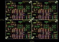
I have a question. Is it a strict requirement to have all the input connectors to go straight into the board? Wouldn't it be much easier to make a really small 100% symmetric PCB layout with in and out using molex connectors? The balanced schematic and the use of quad op-amps easily allow this. And then just use short wires to the XLR/RCA sockets and the switch? You can make the board so small that it will easily fit in between or anywhere near the XLR/RCA connectors if mounting it on the back panel is a requirement. Also, I would try to minimize the bottom layer traces length around the op-amps not to cut the GND plane too much (I hope I've got it right and GND plane is on the bottom layer). I also see that your power traces are of variable width which seems to be a bit arbitrary.
Regards,
Oleg
Hi Oleg.
Yes it was the idea from the beginning to have a board which sat behind the connectors and avoided the need to wire from connector to board. Not that it stops anyone from doing so. All in all it becomes very space efficient. It also means there is a convenient place to mount the toggle switch. The board is 48mm x 65mm and sits 24 mm back from the rear panel of the enclosure - the depth of both the XLR and RCA connectors.
It's a four layer board with the two inner layers ground planes.
On the power traces, I just made the ones which feed more than one final destination a little wider than the rest (24 mil vs 12 mil). I recognise this was probably a bit misguided but it likely has no cost. I can probably still change them.
Last edited:
I do not know how your connectors would behave but central pin of Neutrik RCA connectors that I use has significant free motion until the plug is inserted. So even if the connector case is fixed to the chassis the pins may not be rigidly attached to it. I would check this first.
Take a look at the Cardas GRFA PS RCA connector. It's built like a brick s%^t house.
") I have in my hand a Cardas GRFA S, their short panel RCA jack. I can't even move the centre pin pushing as hard as I can on it with my thumb. I'm very confident it will be the same with the GRFA PS which has this pin encased for an additional 17mm or so. It doesn't 'float' within the exterior barrel. It is embedded in some sort of Delrin like material. But thanks for flagging the point. I've made all the power traces 24mil and uploaded the new version to the board house.
I have in my hand a Cardas GRFA S, their short panel RCA jack. I can't even move the centre pin pushing as hard as I can on it with my thumb. I'm very confident it will be the same with the GRFA PS which has this pin encased for an additional 17mm or so. It doesn't 'float' within the exterior barrel. It is embedded in some sort of Delrin like material. But thanks for flagging the point. I've made all the power traces 24mil and uploaded the new version to the board house.Theta implemented this idea well on their Prometheus amp. High res images of exterior and interior here:
http://thetadigital.com/downloads/images/Theta_Digital_Prometheus_Rear.jpg
http://thetadigital.com/downloads/images/Theta_Digital_Prometheus_Internal.jpg
It was seeing their implementation (and our switch discussion here) which made me change from the perpendicular board I originally had come up with - see post 1. In fact, at one point I was going to source the RCA connectors from them. In the end I decided it was better to not be reliant on a part which turned out to be custom made for Theta/ATI. Of course their board is smaller and simpler as a result of the typology of the Hypex NC1200 amp with its input buffer on the amp module.
Last edited:
Some pics (unfortunately without the RCA connector). Wave footprints made the soldering easy, although at high mag it looks like I used too much solder. Testing to come.
Attachments
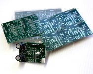
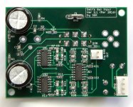
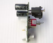
Some pics (unfortunately without the RCA connector). Wave footprints made the soldering easy, although at high mag it looks like I used too much solder. Testing to come.
Very nice boards - congratulations!
Have fun,
Toni
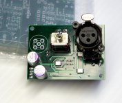
Yes you're right, the input filter goes back to the enclosure.
How does the PCB mounted plastic XLR socket connect to enclosure?
Hi. The NC3FAV1 (link to Neutrik website in post 94) has pin 1 connected to a "pin" in the shell which presses against the chassis when mounted. Here is the photo of the NC3FAV1 connector pictured in the link above. You can see this pin if you look at the bottom right screw socket. From the link above "grounding: mating connector shell to pin1 and front panel". It is why I selected this part.
An externally hosted image should be here but it was not working when we last tested it.
- Home
- Amplifiers
- Solid State
- Self's "5532 Low Noise Unity Gain Balanced Input Stage"