Ok, thank you.
I want to try my self to make some experiments with winding an output transformer for fun, i was not able to find thinner insulation pressboard than 0.1mm and i was curios if you use thinner than this. And for coil bobbin (coil former) i want to use 1.5mm insulation pressboard, what do think will work ok? and here i need to find a way to cut it correctly, maybe with a laser which i don't have it :-( i am asking you these because i saw you have tested already, i hope don't bother you")
If you rely on the dielectric to hold your layer ends, I wouldn't recommend working with something bellow 0.08mm. Although if the paper is waxed, which makes is stronger, you could go to 0.05mm for fine wires, such as 0.13-0.18mm. You could buy Nomex 410, although expensive, on a thickness of 0.08mm.
I'm using 0.1mm for wire diameters 0.2 to 0.5, then 0.2mm for 0.6mm and above.
In art stores, you could find paper with 0.05mm thickness, but it will be quite fragile and foldy.
I'm using pressboard for coil formers, laser cut. 1.0mm for small coils, 1.5mm for medium sized transformer and 2.0mm for very big stuff.
Thank you for the advice given, they are very helpful for me. thinner insulation i found but not paper it is some PET Polyester Film (Heat class: „B”/ 130 °C, Impact tension: 8kV) and don't know what results will give And another option is to use baking paper but the same i don't know what result can get. But... The winter is coming! I will have some free time to do some experiments.
I will have some free time to do some experiments.I agree regarding the baking paper - I haven't had great experience with it - being silicon paper it is quite slippery not only does it not take tape well, if your layers are not perfectly flat, wire tends to slip off the edges, to counter this a reasonable margin is needed which eats into winding space. The old fashion sandwich wrap/tracing paper works ok for me. I have attached a screen shot taken from a book on coil winding that is available as an online loan from the internet archive, gives suggested insulation thickness between wire layers, the other pics show one way of anchoring turns when making a tap in a winding. If you are using a bobbin it is possible to do away with insulation between the layers of wire in each winding, just make sure the winding is even, to keep the voltage gradient between turns as small as possible, this can be done with care, just by hand feeding the wire - it is not uncommon for the primary turns per volt to be as high as 10 to 12 turns per volt so unless you are really sloppy it is unlikely that you'll get more than 50 or 60 volts between adjacent turns, if you are careful this can reduce to a max of less than 20 volts between adjacent turns. Prior to building my coil winder, I wound many transformers by hand this way, a simple low voltage driven spindle with wire fed by hand, the only thing that is a must is an accurate turns counter.


CNC is the next great thing since sliced bread, it allows almost instant setup for near perfect distribution of turns over the coil.
Although the thicker is solid wire the more tricky is to wind it.
Although the thicker is solid wire the more tricky is to wind it.
Attachments
The book is simply called Coil Winding - originally published by the Geo Stevens company - they made and sold coil winding equipment, I don't have a link, but if you go to the Internet Archive and search 'coil winding' the book/s are not hard to find, probably best to use the filter option on the left side of the search page and narrow the search down to texts only - you should find 2 books by Geo Stevens the earlier publication is free to download - the later publication is borrow only for which you'll need to register and log in - if you are keen enough it is possible to 'borrow' and then use your computers 'snip' feature to capture each page as a jpg.
My Aumann winder is still using the original mechanical counter, it does the job - it is ok but not great. The winder was in poor condition when it was given to me - motor needed a rebuild, wire feeder/traverse was damaged and missing one of the stops that reverses the feed, but I managed to make/fix all the parts I needed to get it working, I like the foot speed control and the motor is powerful enough to wind wire up to 1.5mm, which is the thickest I have wound, for some jobs though I still use my stepper controlled home made winder.
My Aumann winder is still using the original mechanical counter, it does the job - it is ok but not great. The winder was in poor condition when it was given to me - motor needed a rebuild, wire feeder/traverse was damaged and missing one of the stops that reverses the feed, but I managed to make/fix all the parts I needed to get it working, I like the foot speed control and the motor is powerful enough to wind wire up to 1.5mm, which is the thickest I have wound, for some jobs though I still use my stepper controlled home made winder.
Sorry for a little off track. I have made a few OPTS and I would like to know what is the leakage Inductance one aims for. I see most commercial OPTs give leaked inductance less than 10mH. In my diy OPTs, I get 9mH and another OPT with same winding pattern gives 22mH.Is there a value(x mH) that says beyond x ,the OPT is unfir for Hifi? Of course I know one has to do frequency sweep to see the high frequency roll off, but Is there any value that makes us one throw the OPT to trash?, without even needing to test it?
P.s. I have used OPTs with higher leakage Inductance also with good audible sonics. So how does the role of leakage Inductance comes to play
P.s. I have used OPTs with higher leakage Inductance also with good audible sonics. So how does the role of leakage Inductance comes to play
Leakage inductance is commonly in relationship with capacitance. Together giving transformer behaviour in the HF end.
That relation causes resonant peek and rolloff after.
Also You can estimate Mutual inductance, and Coupling factor with primary inductance and leakage inductance.
Try to google and calculate based on the measured results.
Key words mutual inductance and coupling factor.
That relation causes resonant peek and rolloff after.
Also You can estimate Mutual inductance, and Coupling factor with primary inductance and leakage inductance.
Try to google and calculate based on the measured results.
Key words mutual inductance and coupling factor.
If you wound 2 identical transformers and there was a large difference in the leakage inductance between them perhaps you should be concerned, my understanding of leakage inductance is that it comes from less than perfect magnetic coupling between the primary and secondary windings, while the winding layout does have an affect on the leakage inductance, the same winding layout on 2 different transformers will not ensure the same leakage inductance for each transformer, as there are physical differences between them. For me, if you run your amp through some standard tests using a scope, signal gen. (and distortion meter if you have one) and it performs well and also sounds good then job well done regardless of the leakage inductance, usually poor performance on tests is seen before you can hear it with a listening test - at the end of the day you aren't listening to leakage inductance but listening to music.
it is not just like put in the chain and listen. At first.
Thry to measure transfer with low imedance and high impedance source
and terminate secondary also with high impedance and lowering after.
A few simple and fast measurements...
.
(Bare in mind to measure or find data about computer or soundcard input resistor because it will be max value of termination.
every other value added will be parallel value of existing input R and this added...)
.
To determine where is the resonant peak if exists, and what happening in bass region. Regardless of the driving impedance and termonation impedance... And see what is the phase shift too. Because transfer almost always measure phase response in the same meas...
.
Then with measured Lp and Ls You can calculate mutual inductance and from resonant peak you can estimate capacitance, and other parameters...
.
Because if You have say +4-6db HF peek @ 14KHz, and -4-6db @ 100Hz, there is no point to listen to this transformer?
Could you please explain a bit more? I measure primary Inductance with a LCR tester( 100hz). I short the secondary wires and take leakege inductance.I can also measure capacitance across the windings. So I now have two values( L and C). I googled for Mutual inductance and I am yet to grasp that... So what else should I measure and calculate the Resonant peak? It would be helpful if the formula is given.
I'm a big fan of using electrostatic screens. Either under the form of windings or foil.
Electrostatic winding screens have one benefit compared to foils, as you can use them to add or substract voltage potentials by connecting different ends. This result is very important for my phase splitter SEP transformer to achieve perfect symmetry between the PP halves over all frequency region.
Using additional screens the right way can help you destroy or reduce unwanted resonances by redirecting capacitances into a less offensive region.
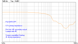
Some troubling dipping resonances can happen when distant secondary layers are capacitively coupled into high-impedance primary layers, considering a low-interleaving, high Ls configuration is selected. The calculated Ls is 17mH.
In a PP transformer, one can get away with high capacitive regions between the secondaries, considering they're equal. However, in SE output transformers, capacitive regions are never equal and this capacitive difference, especially between series connected secondaries can cause a low-frequency offensive dipping resonance. In a sense, PP transformer are easier to achieve better HF response
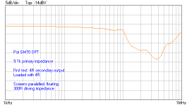
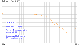
This transformer is designed with a high Ls, low interleave count. Double bobbin single C-core, using 3 P/S interleaves, into a configuration of Px/SS/P2x/S and 4200 primary turns count. Ls dominant roll-off.
There is a very small residual resonance at ~40kHz that could be taken care of by grounding the core and adding additional screen between the two bobbins that would shunt a small amount of residual primary to secondary capacitance, but I decided to leave it this way.
You can observe a quite universal frequency response behavior with different driving impedances - 300R to 4.7k. Little peaking ringing is observed for all configurations.
Electrostatic winding screens have one benefit compared to foils, as you can use them to add or substract voltage potentials by connecting different ends. This result is very important for my phase splitter SE
P transformer to achieve perfect symmetry between the PP halves over all frequency region.Using additional screens the right way can help you destroy or reduce unwanted resonances by redirecting capacitances into a less offensive region.
Some troubling dipping resonances can happen when distant secondary layers are capacitively coupled into high-impedance primary layers, considering a low-interleaving, high Ls configuration is selected. The calculated Ls is 17mH.
In a PP transformer, one can get away with high capacitive regions between the secondaries, considering they're equal. However, in SE output transformers, capacitive regions are never equal and this capacitive difference, especially between series connected secondaries can cause a low-frequency offensive dipping resonance. In a sense, PP transformer are easier to achieve better HF response
This transformer is designed with a high Ls, low interleave count. Double bobbin single C-core, using 3 P/S interleaves, into a configuration of Px/SS/P2x/S and 4200 primary turns count. Ls dominant roll-off.
There is a very small residual resonance at ~40kHz that could be taken care of by grounding the core and adding additional screen between the two bobbins that would shunt a small amount of residual primary to secondary capacitance, but I decided to leave it this way.
You can observe a quite universal frequency response behavior with different driving impedances - 300R to 4.7k. Little peaking ringing is observed for all configurations.
Attachments
So you advice to make electrostatic screen between each plate-end primary of PP transformer and secondary and ground these screens?I'm a big fan of using electrostatic screens. Either under the form of windings or foil.
Electrostatic winding screens have one benefit compared to foils, as you can use them to add or substract voltage potentials by connecting different ends.
Last edited:
On a PP transformer, both plate-end to secondary layers should see equal voltage gradient. I find it unecessary there.
I recommend screens where secondary layers connected in series see different voltage gradients related to the primary layers.
In output transformer with all paralleled secondary layers screens are not necessary, because paralleling secondaries acts as self-screening.
With a good knowledge of screening secondary layers, basically you can build a high - combo count of secondary configuration with the retaining of a stable frequency response.
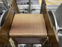
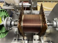
Just finished a copy of a Dynaco Z565 output transformer, for a Dynaco ST35 project I have in mind, the wind has 2 complete primaries connected in parallel, 6400 turns total become 3200 turns once all of the connections have been made - secondary is done in a similar way.
Initial testing was done with standard grade power transformer laminations, I built a mono version of the Dynaco SCA35 power amp so I could do some tests and measurements, so far very pleased with the results, the scope trace pics of 100Hz,1KHz and 10KHz are not too bad considering the laminations were ordinary power transformer type. My M6 GOSS laminations arrived a few days ago so once the varnish/potting is done I'll reassemble with these.


Initial testing was done with standard grade power transformer laminations, I built a mono version of the Dynaco SCA35 power amp so I could do some tests and measurements, so far very pleased with the results, the scope trace pics of 100Hz,1KHz and 10KHz are not too bad considering the laminations were ordinary power transformer type. My M6 GOSS laminations arrived a few days ago so once the varnish/potting is done I'll reassemble with these.
- Home
- Amplifiers
- Tubes / Valves
- Show your transformer work (gallery)