@50AE , what kind of guide tooling you use to straighten 0.6 - 0.8mm wire and make trifilar winding? Some kind of plastic plate with rectangular canal? For monofilar winding I use set of custom 45deg V-groove rollers made from industrial nylon. It helps straighten thick enamel wires, albeit not perfectly for diameter 0.75mm+.
I saw this 6 V-groove roller wire straighten tool on youtube, yet it requires too high torque from spindle motor I don't have. My CNC linear coil winder is driven by 2 synchronized step motors from interrupt driven micro-controller as 2-channel pulse generator. Traditional scheme usually uses servo AC motor (which have much higher torque compared to step motor of similar size) for spindle with encoder to drive shuttle step motor. Replacing spindle motor with more powerful unit is quite difficult and time consuming in my case.
Thanks !
Well, for some reason I don't need straightening of thick wire. I got the issue the other way - straightening fine wire, as I'm aiming for lowest tensioning possible, and low tensioning equals lower control over residual wire distortion. To do that, I'm using a simple trick of feeding the wire diagonally from the tensioner to the feeder. There is a sweet spot angle, depending on the spool and wire type. Ideally, a servo motor rotating the tensioner can be used to keep the sweet spot angle.
As for the bifiliar, trifiliar or more, I just increase the step x the required wire count, then wind a trifiliar layer in three identical procedures. If 1mm wire is needed, I just configure the machine to 3mm step size for trifiliar winding. This works for single layers only.
Yes that was I thought myself but I'm just too lazy for tripple work. When I constructed and build my CNC linear coil winder I missed some moments like necessity for high torque.As for the bifiliar, trifiliar or more, I just increase the step x the required wire count, then wind a trifiliar layer in three identical procedures.
How does lower wire tension affect transformer performance ?Well, for some reason I don't need straightening of thick wire. I got the issue the other way - straightening fine wire, as I'm aiming for lowest tensioning possible, and low tensioning equals lower control over residual wire distortion.
Not much of transformer electrical performance, than the permission of using softer dielectrics with less chance of end layer wire turns crushing the dielectric edge in mid-air and falling to the bottom layer.
Ok now I understand, I haven't had that issue and do like to keep a bit of tension on the wire to keep the wire buildup smaller, the video I linked shows my despooler, it has an overrun brake that stops the spool from spinning once the spindle stops or slows and also a static friction brake with adjustable spring tension, this controls the wire tension, I copied the design from a Douglas Avo coil winder.
For fine wires despoolers, I tried various options, such as funnel/bucket style and rotating despooler (Lundahl style), but the best is building a wisker disc replica. Google wisker disc, you could buy the original too.
After rewinding the 114mm X 65mm 360W PT, said I'd never wind another trafo- (heavy sigh)
This is much smaller project (keep telling myself)- rewinding 6.3V 1.2A PT as a choke. Won't use it for anything- won't throw it away... the conundrum.
So the Q-
The cores in this trafo were held together by some type of glue. I was able to disassemble EI cores carefully w/ Exacto knife- then clean in Mineral Spirits.
When I reassemble- what adhesive? Thought I saw that stated in this thread- now can't find.
Here's what I did find- (clear color option)
https://www.ebay.com/itm/374140702686?
Is this good choice to brush on EI cores when assembling?
Jim
C-clamped the hand crank station from previous project- then stripped original windings from bobbin.
Rewrapped w/ some of original 26ga from ChiFi 720VCT secondary- recycling- keeping out of land fill.
3 hours of hand crank and feed later..
Ended up w/ 650ish winds over 13 layers populating .250" radial room on bobbin-
Pic 1- Wrapped and assembled minus 2 "I" cores- Also shows quick CAD design and band saw cut of frame
Pic 2, 3- Finished front and bottom pics showing frame assembly & layers
DCR 14.5 ohms. Next task to determine inductance
Jim
ps. didn't use glue between lam's- less chemicals is good from health aspect
Attachments


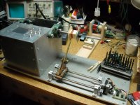
I built a coil winder in 2014 and made a pair of output transformers for a 71A headphone amp.
An Arduino runs the stepper motors. Max winding speed is pretty slow due to the processor limitations.
User Inputs include wire size, number of turns, direction of wind (left to right or right to left).
I probably spent more on the winder than the pair of transformers would have cost, but it was a lot of fun.
Attachments


You can use interrupt based AccelStepper library for much better control of stepper motors from Arduino.An Arduino runs the stepper motors. Max winding speed is pretty slow due to the processor limitations.
I did use the the int based AccelStepper library. The ATMEGA2560 was too slow. Or my coding was inefficient. Either way, If I were to work with it again I would use an ST Micro 32L476 or similar processor.
For my home made winder the spindle drive uses a Renault 16 radiator fan 12V brush type motor with belt drive to the spindle, motor speed control is via a standard Ebay PWM controller. To control the winder I used 2 Picaxe chips as I already had these, one chip does the house keeping, ie start/stop the spindle and count the turns and the othe chip controls the wire feed/traverse, the house keeping chip sends a pulse to the wire feed/traverse chip once every turn, so it can advance the wire feed via a small stepper.
I did try a stepper for the spindle but found they do have some limitations on their max speed so I went with 12V motor instead, this meant extra hardware as I had rig up a spindle and then a belt drive to the motor, the maximum speed I have used is around 800RPM, but it will go much higher.
I did try a stepper for the spindle but found they do have some limitations on their max speed so I went with 12V motor instead, this meant extra hardware as I had rig up a spindle and then a belt drive to the motor, the maximum speed I have used is around 800RPM, but it will go much higher.
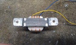
Refreshing the thread with a small cathode stage headphone SE output transformer, deliberately using high primary Rdc for cathode bias by customer request.

Wow, that is a superb lay of the wire: is that wound by hand? If it is I'll fall off my chair : )
Andy.
Andy.
It's machine wound, however it is corrected and compacted via hand. 🙂 It takes some practice to get tight layers with fine wire, tensioners and machine setup are very important for this.
Congrats on the good work - your stuff always looks very professional, yes I agree about machine setup, the thinner the wire the more critical the machine/setup
looks very nice, what's the thickness of insulation paper which you used between layers?It's machine wound, however it is corrected and compacted via hand. 🙂 It takes some practice to get tight layers with fine wire, tensioners and machine setup are very important for this.
Ok, thank you.
I want to try my self to make some experiments with winding an output transformer for fun, i was not able to find thinner insulation pressboard than 0.1mm and i was curios if you use thinner than this. And for coil bobbin (coil former) i want to use 1.5mm insulation pressboard, what do think will work ok? and here i need to find a way to cut it correctly, maybe with a laser which i don't have it :-( i am asking you these because i saw you have tested already, i hope don't bother you 🙂
I want to try my self to make some experiments with winding an output transformer for fun, i was not able to find thinner insulation pressboard than 0.1mm and i was curios if you use thinner than this. And for coil bobbin (coil former) i want to use 1.5mm insulation pressboard, what do think will work ok? and here i need to find a way to cut it correctly, maybe with a laser which i don't have it :-( i am asking you these because i saw you have tested already, i hope don't bother you 🙂
For Arduino check out this library: TeensyStep
It's much better than accelStepper and runs on Teensy, a nice small and very powerful device.
It has a winder class which is perfect for winding applications!
It's much better than accelStepper and runs on Teensy, a nice small and very powerful device.
It has a winder class which is perfect for winding applications!
Last edited:
- Home
- Amplifiers
- Tubes / Valves
- Show your transformer work (gallery)