So true.Wow.... I don't know what Mark does for a living but I bet they don't pay him enough.
I have ordered left and right channel boards. Minimum order is 5 of each so I think I could send you a pairOr failing that anyone in Europe?
")
I will see what customs etc. will be and then I know what your share of the cost would be. Would be sending them from The Netherlands. Send me a mail if this is ok for you
Thanks I will PM you.I have ordered left and right channel boards. Minimum order is 5 of each so I think I could send you a pair
I will see what customs etc. will be and then I know what your share of the cost would be. Would be sending them from The Netherlands. Send me a mail if this is ok for you
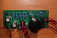
I picked up five each right, left and PS boards from JLCPCB with 2oz copper. I am not sure if the 2 oz copper will make a difference in sound quality but it's DIY. I am planning to use a dual mono configuration, so I will have 4 Left and right channel boards left over and three power supply boards. I paid$109.27 for the fifteen boards including shipping from China. That works out to roughly $7.30 per board. I will ship anywhere in the US using a USPS priority mail envelope which is $9.90. Those interested please send me a PM and we can work out the details.
Regards,
Roy
. I am planning to use a dual mono configuration, so I will have 4 Left and right channel boards left over and three power supply boards. I paid$109.27 for the fifteen boards including shipping from China. That works out to roughly $7.30 per board. I will ship anywhere in the US using a USPS priority mail envelope which is $9.90. Those interested please send me a PM and we can work out the details.Regards,
Roy
I sent you a PM.I picked up five each right, left and PS boards from JLCPCB with 2oz copper. I am not sure if the 2 oz copper will make a difference in sound quality but it's DIY
Regards,
Roy
Anyone been thinking of gain stages for this project ? Sadly as it stands now, I will be feeding this with an output from a 6-24 crossover. I'm guessing the most to be seen from this would be 10vPP resulting in 6 watts ish if my math is correct. The crazy audio neurotic guy in my head thinks 25watts would be nice. I believe this means 20vPP (math again ?). So, one of the Vfet boards/ BA3 gain stage / edcore 5x xformer on its own / wait on the boards from the Burning Amp video? In thinking through these options I discovered that regulation in the 30+range (especially bipolor) is somewhat limited.
Would enjoy some ideas and opinions for various gain stages.
Would enjoy some ideas and opinions for various gain stages.
Oops...Should not have been using peak to peak. Another silly mistake, I get ahead of myself all to often. Sorry bout that. 6-24 has 24v single rail supply..so I should have said 10v peak ( on its best day , maybe). I would love to think the edcore 600/15k could go in there and solve everything, but it can't be that easy. Would that load down and cause grief ?
Thinking about this with the point in mind not to cascade many gain stages, with the aim to avoid complex distortion. Keep the follower clean with just the SIT (just a follower). Use a preamplifier with sufficient voltage gain. Alternatively implement the voltage gain stage with the SIT follower and use the beast as an integrated amplifier. No preamplifier required. Of course, with electronic crossovers in the equation this might change, and voltage gain and preamplifier (B-1) might be the better and more practical solution.
I am sure it is possible to use a SMPS. Others have used them in power amplifiers. They have their advantages, but they have their disadvantages too.
However I have no experience with them in amplifiers. I prefer to build with power supplies that I understand and can trouble shoot and fix. I can't do that with SMPSs. They are beyond my understanding.
However I have no experience with them in amplifiers. I prefer to build with power supplies that I understand and can trouble shoot and fix. I can't do that with SMPSs. They are beyond my understanding.
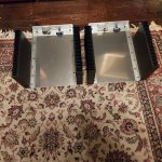
Two sizes of heat sinks?
The mosfet and SIT dissipate approximately equal amounts of heat.
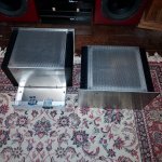
There will be heat inside of the chassis that needs to be evacuated, so vents in the top and bottom plates would be most helpful. The electrolytic capacitors need to be kept cool. ❄️❄️❄️
The mosfet and SIT dissipate approximately equal amounts of heat.
There will be heat inside of the chassis that needs to be evacuated, so vents in the top and bottom plates would be most helpful. The electrolytic capacitors need to be kept cool. ❄️❄️❄️
Optical Illusion...All sinks are the same 5Ux300mm. Top will be mesh and there will be a Keyway type slot on the back panel. I also have the Noctua fans and a temperature controller that will run off the extra 12v coil from the transformers (good idea you had there). Plan to stand the Caps on a bed of silicone foam and blast the fan directly over them. Hopefully the cheap control board works out...and wont introduce any buzzes whirs or clicks.

Ben, you mentioned placing an 8ohm load in place of the SIT to test operation of the mosfet current source devices as well as testing no load SIT removed. Just for clarification, no load test is observing variable voltage control of the mosfet in an open circuit ? Test with load would place dummy load between SIT Drain and Source, observing similar ability to control voltage....and not letting out magic smoke ? Do I have this correct....I'm still drilling and sanding so testing is a ways off, but wanted to get this straight.
As always...Thanks for your work is in order.
As always...Thanks for your work is in order.
I like testing in stages. It's easier to catch errors and it jeopardizes less parts. The test with no SIT installed is with a DBT to check for shorts. Then test with a resistor test load in the SIT's place to test the current source circuit and bias circuit. So the SIT does not get installed and powered up until we know that the current source and bias supply are working properly.
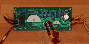
As for the stuffing of the boards, the most important thing is to elevate the 0.1R 3W resistors at least 15mm or even 20mm above the board, as they will get hot. Although not critical, orientation of the trimmer resistors in the recommended way will allow for increasing Iq when making clockwise adjustment.
As for the chassis, there should be venting in the top and bottom plates so hot air inside the chassis can escape.
I will post some build tips shortly and provide more information.
Meanwhile, the trimmer orientation:
Attachments
- Home
- Amplifiers
- Pass Labs
- Single Ended Tokin SIT THF-51S Common Drain Mu Follower Amplifier, 45W?