
The diyAudio store heatsink page gives the C/W for the 300x165x40 as 0.31. It could be borderline. It really depends on what temperature differential the C/W is based on. We want to keep the maximum heatsink fin temperature to 55C. If ambient temperature is assumed to be 25C, the temperature differential is 30C. If you expect to run the amplifiers in a hotter room, then the temperature differential is lower.
The THF-51S Vds is 33V and Iq is 3.0A, so 99W need to be dissipated. If C/W of 0.31 is based on a temperature differential of 30C, then it just makes it.
But the C/W of 0.31 may be optimistic. I have seen heatsink specifications that specify their C/W based on a higher temperature differential. Higher temperature differential will yield a lower C/W (lower C/W is better) and makes the heatsink look good on paper, but will not work as well when the maximum temperature is 55C.
I have no experience with this heatsink so I do not know if it has enough capacity. Perhaps someone on diyAudio has used this heatsink and can comment on its capacity.
Or if you already have the heatsinks, you can test them as Pinholer suggested.
Yup, My M2 clone uses this size chassis and sinks are 50-52°C. IMO, 100W is to much for 300 x 165 x 40 size HS without active cooling.70W for 4U/300deep Modu is bloody borderline, by actual experience
from experience:
4U/300 good for 70W
4U/400 good for 90W
5U/500 good for 120W
all of them with Babysitter in Summer, to ease occasional thinking about caps inside
I did wrote several times, my stance is that 4U/400 needs to be basic Store model (not 4U/300)
Much better solution, thinking about dissipation but also increased space inside
Thank you very much !from experience:
4U/300 good for 70W
4U/400 good for 90W
5U/500 good for 120W
all of them with Babysitter in Summer, to ease occasional thinking about caps inside
I did wrote several times, my stance is that 4U/400 needs to be basic Store model (not 4U/300)
Much better solution, thinking about dissipation but also increased space inside
5U/500 is on the way to me at the moment, let's see when I can start playing with it -- when my small daughters may allow.
I just bought the 5U/500 from Modushop. I couldn't see a way of doing that at the DIYAudiostore.com. Black Friday sale was expiring today so I pulled the trigger. Is that where you got yours and did you find a way to specify the DIYAudio UMS drilling for the heatsinks?Thank you very much !
5U/500 is on the way to me at the moment, let's see when I can start playing with it -- when my small daughters may allow.
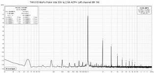
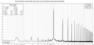
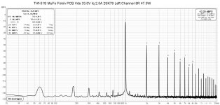
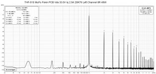
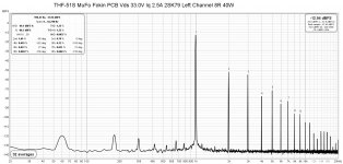
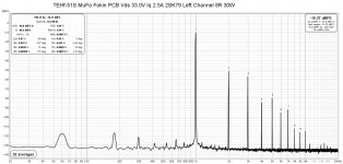
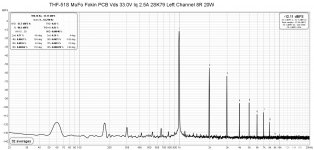
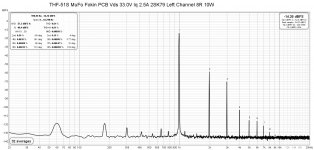
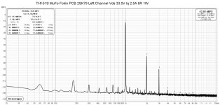
I measured the left channel with Vds 33.0V and Iq 2.5A. At low power output, the distortion measured a bit lower and was higher at high power output. The lower distortion at low power output could be due to variations in the test from day to day, but who knows. The distortion at higher power output is expected. But it still is quite good. I am listening to this right now and it sounds good. However I probably am only using the first Watt.
My 2SK79 preamp contributes to the distortion too. I don't have a very low distortion preamp to use to test follower amps to determine their true distortion levels.
My 2SK79 preamp contributes to the distortion too. I don't have a very low distortion preamp to use to test follower amps to determine their true distortion levels.
Attachments
-
 THF-51S MuFo Fokin PCB Left Channel ACP+ Vds 33.0V iq 2.5A 8R 1W.jpg238.9 KB · Views: 85
 -
 THF-51S MuFo Fokin PCB Left Channel 2SK79 Vds 33.0V iq 2.5A 8R 50W.jpg243.1 KB · Views: 82
 -
 THF-51S MuFo Fokin PCB Left Channel 2SK79 Vds 33.0V iq 2.5A 8R 47.5W.jpg241.6 KB · Views: 68
 -
 THF-51S MuFo Fokin PCB Left Channel 2SK79 Vds 33.0V iq 2.5A 8R 45W.jpg241.1 KB · Views: 73
 -
 THF-51S MuFo Fokin PCB Left Channel 2SK79 Vds 33.0V iq 2.5A 8R 40W.jpg241.4 KB · Views: 67
 -
 THF-51S MuFo Fokin PCB Left Channel 2SK79 Vds 33.0V iq 2.5A 8R 30W.jpg239.8 KB · Views: 75
 -
 THF-51S MuFo Fokin PCB Left Channel 2SK79 Vds 33.0V iq 2.5A 8R 20W.jpg239.3 KB · Views: 70
 -
 THF-51S MuFo Fokin PCB Left Channel 2SK79 Vds 33.0V iq 2.5A 8R 10W.jpg239.2 KB · Views: 71
 -
 THF-51S MuFo Fokin PCB Left Channel 2SK79 Vds 33.0V iq 2.5A 8R 1W.jpg239.9 KB · Views: 80
Yes, I also ordered at Modushop.
I didn't want it to have the UMS drilling, as I wanted to do it myself -- and I'm not sure if a UMS compatible amp would reside there.
If you want a modification, you can purchase your own customization as well. Look for customization there at modushop, they do it at a very high quality level.
Kind regards
Matthias
Nope, that won't fit the UMS layout. So that will save me 62 Euros for pre-drilling. I guess I will have to perfect my screw tapping skills. FWIW this is a link to the UMS Specs. https://cdn.shopify.com/s/files/1/1006/5046/files/universal-mounting-specification-v2.1.pdfI don't know.
The amplifier boards have four holes in a 140mm x 50mm grid.
Per Ben:Two modushop 300mmx210mmx40mm heatsinks per channel should work:
I scraped my original design and had 4 of these purchased the night before you posted.... It was nice to get a bit of conformation.....and I Always wanted mono blocks. Now I need to build a shelf to make room for the mini infernos (extraneous costs be damned I'm too far in)!
Check my reasoning here please: 100 watts(per device) x .18C =18 degree rise + 25 ambient =43C. He'll that's merely luke warm , I must be missing something.I
Last query of the night.. Should we be thinking about thermal isolating the sinks from the chassis ?
All the best
Your calculation is correct. What may questioned is the 0.18C/W number. The C/W can vary widely depending on the temperature differential that the measurement was based on. Attached is a specification sheet for a heat sink where the information is provided . As you can see they provide numbers and graphs so that an educated decision can be made.
There is no need to thermally isolate the heatsink from the chassis. The heat sinks should be electrically connected to the chassis and chassis ground for safety.
There is no need to thermally isolate the heatsink from the chassis. The heat sinks should be electrically connected to the chassis and chassis ground for safety.
Attachments
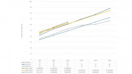
For the Modushop heatsinks, Gianluca was kind enough to publish their internal study in Pico's "Toxic Masculinity" chassis thread. It's in Italian, but most of it is fairly intuitive w/o translation. You can see that they took the heatsinks up to some (IMO) 'high' temperatures in order to find their saturation points and calculate their thermal coefficients. I extracted some of the data visually for my own purposes and fun and to see how close my own sinks perform in my own environment. Note - the ambient temp in their room was significantly higher than it is in my home. It was not directly published in the study, but I made some assumptions from the time notes in the data along with the start points.
So, this may be totally off...
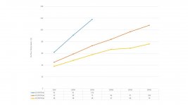
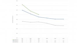
First is the temp shown on the fins. Second is the temp shown on the sink itself. Third is the tempco calc from the fin data. They use the max saturation temps, but to me, I am more concerned with the temp at the fins. It's important to note that they used an idealized situation with a heater bar vs. unique devices and excellent thermal transfer across an entire chassis. The test was not done simply on a lone heatsink.
tl;dr - YMMV, but my anecdotal temps are reasonably close when I put it into the regression. (I don't actually own any chassis in the sizes used in the study). Also, it clearly illustrates that the coefficient changes with thermal loading (as expected) and shows the slopes etc. which can / may be useful to some.
See the "Toxic Masculinity" thread for the full study - no need to double it up.
Hope it helps.
So, this may be totally off...
First is the temp shown on the fins. Second is the temp shown on the sink itself. Third is the tempco calc from the fin data. They use the max saturation temps, but to me, I am more concerned with the temp at the fins. It's important to note that they used an idealized situation with a heater bar vs. unique devices and excellent thermal transfer across an entire chassis. The test was not done simply on a lone heatsink.
tl;dr - YMMV, but my anecdotal temps are reasonably close when I put it into the regression. (I don't actually own any chassis in the sizes used in the study). Also, it clearly illustrates that the coefficient changes with thermal loading (as expected) and shows the slopes etc. which can / may be useful to some.
See the "Toxic Masculinity" thread for the full study - no need to double it up.
Hope it helps.
Attachments
I realized I do have some real life experience with the 300mm x 210mm x 40mm heat sink. I have them in my 193V choke loaded 2SK180 follower (originally common source, then changed to common drain), dissipating 85W. They are warm to the touch, with ambient temperature in the low 20s degrees C.
2SK180 Amp with 300mm x 210mm x 40mm Heat Sink
2SK180 Amp with 300mm x 210mm x 40mm Heat Sink
- Home
- Amplifiers
- Pass Labs
- Single Ended Tokin SIT THF-51S Common Drain Mu Follower Amplifier, 45W?