The monster sounds neutral and powerfull. The baby sound much warmer due to the tube linestage.
With the same line stage they sound the same until the baby runs out of power. Kypton ND ips in the monster and Kypton V (sansui) in the baby.
The monster have 80V rails and the baby 56V so there's a big difference in power.
With the same line stage they sound the same until the baby runs out of power. Kypton ND ips in the monster and Kypton V (sansui) in the baby.
The monster have 80V rails and the baby 56V so there's a big difference in power.
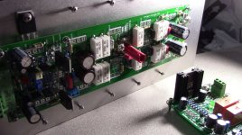
Have you finished the build of the parts shown here? Just Wondering.
sorry for the late responds since I'm in Puerto Rico is difficult to get tools I need to purchase a drill press for the heat sinks I ordered I have on my channel a PayPal button to get donations I really hate to do that but my money is getting lower
my project is stuck because of that I just to pass time re-done the Arc Welder to have 2 more pairs looks cool YouTube
does audio transistors need a specific torque?
hi guys silly question from me does audio power transistor need a specific torque on a transistor to be adjusted correctly I know that there is not a device that can tell how much pound torque you can apply to a audio power transistor but got me thinking that is my Arc Welder build I'm going slowly but is there is coming along
hi guys silly question from me does audio power transistor need a specific torque on a transistor to be adjusted correctly I know that there is not a device that can tell how much pound torque you can apply to a audio power transistor but got me thinking that is my Arc Welder build I'm going slowly but is there is coming along
Attachments
"Typically 15 in-lb torque is adequate for fastening a TO-220
device on the heat sink and obtains the best (lowest) possible
thermal resistance value. Use of a heat sink compound
improves the thermal resistance by almost 0.6 C/W, but
electrical isolation between part tab and heat sink increases
the thermal resistance of the interface by a factor of 3 to 6....."
I would assume that the same applies for other size packages too.
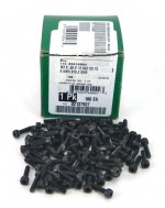
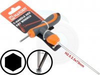
15 in-torque? oh ok, on the photo I post you see regular phillips screws I was thinking to use hex screws 2.5 mm so I can then adjust them with a T-handle hex key for better torque control I'm aware of be careful here no to damage the body of the power transistor by over torque them too much I having this project for almost 2 years and now that I have the correct tool now I can make those difficult M3 holes that can not be done by hand and I want this amplifier to be correctly installed
Attachments
I use a torque screwdriver set for 8 inch-pounds. I think that's about right. Motorola (and On-Semi) have an app note that deals with mounting semiconductors. Everything you need to know is in there. I'm trying to find it for you.
-Chris
Edit: 15 in-lb sounds far too high. The app note is careful to make the point that over-tightening transistor packages can break the die inside. TO-220 parts are set for 6 in lbs.
-Chris
Edit: 15 in-lb sounds far too high. The app note is careful to make the point that over-tightening transistor packages can break the die inside. TO-220 parts are set for 6 in lbs.
I use a torque screwdriver set for 8 inch-pounds. I think that's about right. Motorola (and On-Semi) have an app note that deals with mounting semiconductors. Everything you need to know is in there. I'm trying to find it for you.
-Chris
Edit: 15 in-lb sounds far too high. The app note is careful to make the point that over-tightening transistor packages can break the die inside. TO-220 parts are set for 6 in lbs.
thank you I appreciated that
Hi Juan,thank you I appreciated that
If you want to do it right you need to use a piece of Aluminum flat bar.
This allows the clamping force that the M3 screw puts on the transistor to be distributed across the entire face of the transistor and not just locally were the washer is. It also allows for better thermal connection between the transistor and the heatsink.

Hi everyone,
I hope this link lasts for a while. Grab it and save it to your hard disks or whatever you are using. It really is the definitive guide to attaching power devices to a heat sink.
https://www.onsemi.com/pub/Collateral/AN1040-D.PDF
The actual search term is "AN1040-D". That is the name of the application note. This is a 24 page document packed with good information. Read it through, even if you have to force yourself.
This document was originally written by applications engineers at Motorola and appears to have been refreshed recently. I hope they keep it refreshed to cover modern developments.
-Chris
Hi Stuart,
Well, not always. Use of a "U" channel is better as it doesn't bend as much. A steel one would be best, but harder to cut and drill. You can also use spring clips (which are great as they control the pressure instead of the technician). That application note covers these options as well as they are all valid.
The problem I see most often in practice is excessive pressure applied that bends the bar, and that causes the pressure to be concentrated on the outer edges. The next most common thing seen is stripped holes. Same problem, the operator of the screwdriver.
If you get a chance to use a torque screwdriver, you will be surprised by how little pressure is needed. Just past snug is how I would describe it, certainly not cranked down. All you need to do is firmly press the two surfaces together enough to get any air squeezed out. If you are going for maximum cooling, then look at the surface roughness and attack that instead of tightening the screw tighter. In fact, when the mounting screw is over-tightened in most cases you actually increase thermal resistance. Counter-intuitive?
-Chris
Hi Stuart,
Well, not always. Use of a "U" channel is better as it doesn't bend as much.
Hi Chris, Sorry mate... but I disagree. You want something that will bend and conform to the surface that its being fastened against. All transistors have tolerances. The thickness of the transistors package may vary from one transistors to the next. Lets say the first and third transistor is 4mm thick and the second transistor in between the first and third transistor is only 3.9mm thick if you use a very strong "U" Shaped section it won't conform and bend down well to the second transistors. So if you are using torque wrench / screwdriver to fasten the transistors it will go off well before the transistor is secure.
As a engineer I need to account for this sort of thing all the time in the machinery that I design.
Hi Stuart,
No, I'm not wrong.
You would generally use a compliant surface between the package and bar. Cardboard actually works very well for this (non-corrugated of course!). If you over-tighten the bar, it will droop between the parts and arch over the flat surface when over the devices. I have seen this often enough in practice. This is very popular in car amplifiers in North America.
Please read the application note as it covers your favorite method as well as most others I have seen. There is data to back up the claims included, so you can see for yourself. Given that a major manufacturer of semiconductors for longer than I've been alive (I think) has compiled all this information, and they have used real engineers for the task, they just might have something to say on the subject.
Anyway, the information is there. Don't argue with me, but I can confirm their findings in over 40 years of practice in the field. That's why I use a torque driver (and invested to buy the darned thing). Not only do I own said tool, I use it all the time when installing power semiconductors or anything else that has recommended torque values. I have actually seen warped transistor packages (some horribly) over the years.
I do agree that many times, using a bar can distribute the mounting force evenly, but only when a compliant material is used between the bar and semiconductor package. As soon as one of these bars deforms though, it is junk and must be replaced. A bare clamping bar should be avoided as there are problems as you have indicated, and I agree with. You absolutely do require a compliant surface between the bar and semiconductor package. You should also include a torque specification for tightening that bar.
-Chris
Are you two talking about the same mounting arrangement? What Chris is describing sounds like how they do it in car amplifiers, the fixing screws between the transistors. Stuart is using the flat bar as a flat washer, the screw goes through the transistor. Less likely to bend the bar but still quite possible.
Hi Stuart,
No, I'm not wrong.
Hi Chris, I'm definitely not saying that you are wrong. I'm just saying that I disagree that a strong "U" Shaped section is better than a flat bendable section.
All of the points you raised and discussed are very valid and I guess need to be accessed at the time depending on transistors package, Heatsink, location and proposed mounting technique.
Thank you for all those extra tips.
I have downloaded the document and will read it tonight if I get time.
Hi Jeff,
Ah, I didn't realize Stuart was using the bar as a washer. Thank you for pointing that out Jeff.
That should work, however it does force you to release all the transistors to work on one. This can happen if you had mounted regulators along with outputs or other mixed I'd just as soon use a washer. Something else I have seen in practice.
-Chris
Hi Stuart,
I completely misunderstood how you were using the bar. The image of my assumption came instantly when I considered using a bar. The fasteners are located between the power devices when using the bar as a clamp and that is where it tends to bend when over tightened.
I had never considered using a bar in the manner you are, so something to look at for me. As for the article, I am reading it again as well. It never hurts to refresh a memory.
-Chris
Hi Jeff,
Ah, I didn't realize Stuart was using the bar as a washer. Thank you for pointing that out Jeff.
No worries Chris. It was good to discuss and bring up those other points so other members can benefit.
Hello guys I tested the Slewmaster 5P OPS with the Wolverine IPS driver board with 55V DC rails and I have a bit of a problem on the bias adjustment some how I can not get it to see the final adjustment I was able to get it to about 24mV but when I try to re-check all over I don't see any measurements on the DMM is 0.001mV but is so odd I change the batteries of both of my DMM and they are fine is this is because has double bias transistors? I'm really confuse oh yeah I initiate the boards first with a 100W light bulb all ok then remove the dim tester and plugin the transformer and check bias is so weird does some one have the same problem?
Hello guys I tested the Slewmaster 5P OPS with the Wolverine IPS driver board with 55V DC rails and I have a bit of a problem on the bias adjustment some how I can not get it to see the final adjustment I was able to get it to about 24mV but when I try to re-check all over I don't see any measurements on the DMM is 0.001mV but is so odd I change the batteries of both of my DMM and they are fine is this is because has double bias transistors? I'm really confuse oh yeah I initiate the boards first with a 100W light bulb all ok then remove the dim tester and plugin the transformer and check bias is so weird does some one have the same problem?
Hi Vargas, something is wrong.
You need to set the bias with no bulb tester, in normal working conditions.
Set 24mV, wait for around half an hour (you can listen to the music in the meantime), then readjust it again.
After you play some music at high volume - the heatsinks get hotter - the bias may go down a little bit. Then, if you leave it idle, it will come to 24mV again.
It will never go down to zero though.
Cheers,
Valery
- Home
- Amplifiers
- Solid State
- SlewMaster Builds