Clearly I need to tweak the thermal compensation temperature coefficient to better control the OPS bias, but overcompensated is at least erring on the safe side.[/SIZE]
[/SIZE][/SIZE]
[/SIZE]
Would the bias circuit perform better if Q104 wasn't mounted on the heat sink? Don't mosfets react opposite to BJTs with heat?
Would the bias circuit perform better if Q104 wasn't mounted on the heat sink? Don't mosfets react opposite to BJTs with heat?
Laterals - yes, react opposite, but HEX-FETs - no. Still require the thermal feedback.
Would the bias circuit perform better if Q104 wasn't mounted on the heat sink? Don't mosfets react opposite to BJTs with heat?
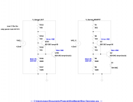
For the Hexfets (vertical MOS) we still need thermal compensation. The issue is the BJT spreader we use to get the bias voltage has a temperature coefficient of about 26mV/°C where we would prefer something closer to 13mV/˚C (maybe a little higher, but not too high). I'm thinking inserting a non-thermally coupled diode into the emitter leg of the main OPS VBE transistor and adjusting the balance between the driver VBE and the OPS VBE just might be the ticket to thermal compensation bliss. I may elect to try Terry's piggy-back technique to make the response faster too.
I'm thinking inserting a non-thermally coupled diode into the emitter leg of the main OPS VBE transistor and adjusting the balance between the driver VBE and the OPS VBE just might be the ticket to thermal compensation bliss.
May be RED LED with 2V forward voltage suitable for this purpose.
Well, so far so good.
I added a 1N4148 diode in series with the main VBE transistor emitter and mounted that device onto the nearest output MOSFET by flying it on twisted wires. The bias current is much more stable now, only just a little overcompensated and that may be the result of my attaching the diode too close to the VBE transistor. At least the bias is not dropping by almost half but rather much less change now.
I added a 1N4148 diode in series with the main VBE transistor emitter and mounted that device onto the nearest output MOSFET by flying it on twisted wires. The bias current is much more stable now, only just a little overcompensated and that may be the result of my attaching the diode too close to the VBE transistor. At least the bias is not dropping by almost half but rather much less change now.
Last edited:
Can someone answer me what the advantages would be to using these lateral or vertical mosfet transistors is? I was thinking about Lazy Cat's VSSA and the fact that I think he used one pair of lateral mosfets and was producing 100 watts output. With five pairs would this be a simple multiple of that or am I missing something on that score? Would this Slewmaster become a 500 watt amplifier with five pairs of lateral transistors?
Can someone answer me what the advantages would be to using these lateral or vertical mosfet transistors is? I was thinking about Lazy Cat's VSSA and the fact that I think he used one pair of lateral mosfets and was producing 100 watts output. With five pairs would this be a simple multiple of that or am I missing something on that score? Would this Slewmaster become a 500 watt amplifier with five pairs of lateral transistors?
Lateral more rugged then vertical, it have zero temperature coefficient around 150 mA drain current. I think it more linear, too (with same loop gain).
I think, Lazy Cat use lateral from exicon and EF driver current around 30 mA. Something like http://www.exicon.info/PDFs/ECW20N20-Z.pdf
Last edited:
The MOSFET thing is just an experiment, the primary project is still a BJT EF3. Vertical types are the only ones that are suited to the board due to their effective pinout compatibility. Laterals won't fit and aren't a topic of discussion. Other verticals are certainly an option, if you are inclined to experiment then by all means try whichever devices you see fit.
R103 and R107 are 100Ω and 2.2kΩ respectively, but this is quite overcompensated. Running on +/-45V rails the OPS bias starts off at 170mA per pair and takes 30 minutes to settle to 90mA per pair on my smallish heat sink that reaches a terminal temperature of 41°C (a 16°C rise over ambient). The small driver heat sink operates at about 30°C. Clearly I need to tweak the thermal compensation temperature coefficient to better control the OPS bias, but overcompensated is at least erring on the safe side.
Tried red LED at the emitter of Q104 (as Bimo suggested). R107 = 680R. Sensitivity is much closer to the right one. On cold power-on quiescent current starts at around 85mA and settles at 60mA in a few minutes.
Cheers,
Valery
Tried red LED at the emitter of Q104 (as Bimo suggested). R107 = 680R. Sensitivity is much closer to the right one. On cold power-on quiescent current starts at around 85mA and settles at 60mA in a few minutes.
Cheers,
Valery
Can you show that on the schematic so we can see what you are doing?
Thanks, Terry
Tried red LED at the emitter of Q104 (as Bimo suggested). R107 = 680R. Sensitivity is much closer to the right one. On cold power-on quiescent current starts at around 85mA and settles at 60mA in a few minutes.
Cheers,
Valery
I read Bob Cordell's book that mosfet like run hot (high quiescent current). Lazy Cat set 200 mA drain current on VSSA.
Valery, can you set the quiescent current to 150 mA? I want to know if there is any audible difference. Thank you.

Did you decide to leave R107 @ 100R?
It shouldn't bee too difficult to install the diode since I use wires for Q103 anyway.
One good thing about having to wait for parts is that you guys are working out the issues before I got a chance to jump in too fast.
Thanks, Terry
I left R107 at 100R and I used R103 as a 2K2. My diode is soldered in place of the emitter lead, with the wires attached as if the transistor lead wasn't trimmed. This may be too close to the source of heat, I suggest finding a way of inserting it so it is not being heated as much. Maybe bring the wires through the screw hole and placing the diode on the top side of the board.
I left R107 at 100R and I used R103 as a 2K2. My diode is soldered in place of the emitter lead, with the wires attached as if the transistor lead wasn't trimmed. This may be too close to the source of heat, I suggest finding a way of inserting it so it is not being heated as much. Maybe bring the wires through the screw hole and placing the diode on the top side of the board.
I thought I would just drill a small hole next to the emitter pad and feed the anode lead through that and solder to the emitter wire, and then solder the cathode directly into emitter pad. Should be easy. I like the idea of using an LED if it works.
- Home
- Amplifiers
- Solid State
- SlewMaster Builds