OS,
Have a great trip to those Smokey Mountains. Looking forward to your return to the thread when you are ready. Perhaps things will surprise you when you come back on.
Steven
Have a great trip to those Smokey Mountains. Looking forward to your return to the thread when you are ready. Perhaps things will surprise you when you come back on.
Steven
OS, i wish a good travel 🙂🙂🙂Hey OS, going to miss you. Hurry back. In the mean time, if Jason will keepp cranking out the gerbers, then we will have plenty of action around her as everyone tries to help me figure out what I've one wrong. 😱 Post some pictures of the mountains. 😀
Blessings, Terry
Terry have you tried to adjust trimmers in opposite rotation each other for offset adjustment?
Hi Thimios,
I can adjust to zero offset but by the time it gets there the one side running way hotter than the other. Something is wrong somewhere. It reminds me of a peeceebee that I built. The offset would change drastically as the vas would heat up. I matched all of the transistors except the VAS so I guess it's time to replace those. I'll replace them in the morning and see how it goes.
I can adjust to zero offset but by the time it gets there the one side running way hotter than the other. Something is wrong somewhere. It reminds me of a peeceebee that I built. The offset would change drastically as the vas would heat up. I matched all of the transistors except the VAS so I guess it's time to replace those. I'll replace them in the morning and see how it goes.
Terry,
the only what can cause voltage across R2, is flowing current . And the only source of this current can by base current Q1,Q2. If Q1,Q2 are beta (the same as h21) matched, base currents should compensate, and the only current flowing through R2 is current difference between base currents Q1,Q2. If voltage across R2 is about 0,5V, Q1,Q2 bases current difference must be about 50uA, and this is way too much, normaly it should be "something" lower than 1-2uA. If this current (and so voltage, too) is after switch only slowly increasing, here is something faulty( e.g transistor with too low Uce, ouside specs, or faulty). Disconnect signal source and short input pins, and try to measure DC. If it will be still here, than short R2 (base Q1,Q2 direct to signal ground) and measure again. Try to change input transistors for new ones.
the only what can cause voltage across R2, is flowing current . And the only source of this current can by base current Q1,Q2. If Q1,Q2 are beta (the same as h21) matched, base currents should compensate, and the only current flowing through R2 is current difference between base currents Q1,Q2. If voltage across R2 is about 0,5V, Q1,Q2 bases current difference must be about 50uA, and this is way too much, normaly it should be "something" lower than 1-2uA. If this current (and so voltage, too) is after switch only slowly increasing, here is something faulty( e.g transistor with too low Uce, ouside specs, or faulty). Disconnect signal source and short input pins, and try to measure DC. If it will be still here, than short R2 (base Q1,Q2 direct to signal ground) and measure again. Try to change input transistors for new ones.
Last edited:
Hi BV,
Thanks for hanging in here with me. I could just toss this but I want to learn something. Everytime a solution is found I get a little better picture of how a circuit works. This makes sense that if Q1 or Q2 is faulty that it might change slowly as the circuit warms up. they are thermally tied together. I will replace them first thing. I did take the measurements with the input shorted but I didn't try shorting R2. I'll wait to try that until after I have replaced Q1/2.
Thanks again, Terry
Terry I doubt that this will solve your problem, but looking at the picture of the underside of your board, those grey film caps look quite melted in parts. If you've damaged the dielectric (what it looks like especially on the right one) they could be faulty. Try checking them to see if they measure within spec. Some caps are very susceptible to this and will measure as a short when damaged.
spooky more datails measurments
Spooky measurements.
Matt and Gareth Ingram, look here.
Any other opinion is useful,
Spooky measurements.
Matt and Gareth Ingram, look here.
Any other opinion is useful,
Attachments
-
 LOOP TEST.JPG93.7 KB · Views: 459
 -
 20V RMS 4R DISTORTION.JPG118.2 KB · Views: 183
 -
 20VRMS 4R.JPG94.8 KB · Views: 191
 -
 20V 7R DISTORTION.JPG121.2 KB · Views: 204
 -
 20V 7R LOAD.JPG95.5 KB · Views: 427
 -
 27V DISTORTION.JPG112.3 KB · Views: 436
 -
 27V.JPG95.4 KB · Views: 441
 -
 LOOP DISTORTION.JPG119.9 KB · Views: 454
Last edited:
For a start here's Self on amplifier distortion mechanisms.
Distortion In Power Amplifiers
From the graphs, where there's a load connected, you've definitely got what could be severe induction based distortion going on. Now this could be inside the amplifier itself, or it could be because currents are flowing where you don't want them to. You've got the classic distortion gets worse with rising frequency and it gets worse as the current increases.
It might be informative to see a distortion sweep at a low output level, one where the amplifier should still be within class A, say 1 watt into an 8 ohm load. Class A is magic in that it eliminates certain distortion causing mechanisms and can help in isolating where a problem might be.
The most troubling part is the high distortion without any load connected. Usually you see problems of implementation and measurement set up when the load is connected, this is because it makes large currents flow and perhaps flow where you don't want them to. Without the load connected this tends not to happen and everything can appear great.
If you run the distortion sweep at 1 watt with the amp biased into class A it would be interesting to see what the performance is like both with the 8 ohm load connected and with it disconnected.
Some issues within amplifiers, that appear without the load connected, are voltage dependent only. That is resistors/capacitors in the feedback network, or the resistors used within your resistor divider before the sound card. If you lower the output voltage of the amplifier this will reduce these effects significantly and it should improve the performance.
I am no expert on these things or anywhere near that but couldn't some of the distortion product we are seeing here be caused simply by the test leads or setup? A few inches of parallel lead wires could cause a fairly large inductance current to be picked up and shown in the results. Can we see how the test was set up and under what the conditions are? I have seen this talked about in so many other threads that it was a simple test setup problem or a temporary wiring situation causing a false test result.
Terry I doubt that this will solve your problem, but looking at the picture of the underside of your board, those grey film caps look quite melted in parts. If you've damaged the dielectric (what it looks like especially on the right one) they could be faulty. Try checking them to see if they measure within spec. Some caps are very susceptible to this and will measure as a short when damaged.
Yeah they got touched a few times with all the adding and removing parts. I pulled them and measured them with my cap meter. They measure fine. I tried it with them in circuit and out. No change. I replaced Q1 & Q2 with carefully matched parts. No change. I replaced the VAS transistors. No change. I'm going to let it rest for a few days. I have something new to play with. My Laserjet came yesterday so this morning I etched some Wolverine boards. Next step is at the drill press. Reminds me of the good ol' days. 😀
Blessings, Terry
Attachments


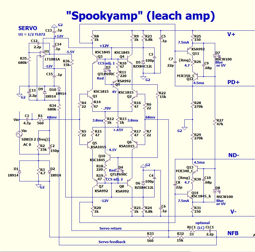
I think, in posted measurments it is mostly caused by excessive resistive and capacitive loading of VAS. It is very crude "compensation". Where is actual schematic of "spooky"?
Yeah, I was searching for the Spooky foil pattern and couldn't find it. There must be one because Thimios built it. Hopefully he will see this and chime in.
Blessings, Terry
Blessings, Terry
The attachments are all here, just 'buried'. When viewing the thread listing in 'Solid State' you will see a paper clip icon beside threads with attachments. Clicking that lists all attachments in the associated thread alphabetically, so you can find attachments more easily if you know approximately what you are after.
The Spooky Amp schematic:
http://www.diyaudio.com/forums/atta...ter-cfa-vs-vfa-rumble-spookyampv1.2schema.jpg
The Spooky Amp schematic:
http://www.diyaudio.com/forums/atta...ter-cfa-vs-vfa-rumble-spookyampv1.2schema.jpg
Last edited:
Thank you Pavel. Would the ground loops be between the amplifier under test and the sound card and not necessarily from the amplifier circuit itself?
Spooky is on the post #803I think, in posted measurments it is mostly caused by excessive resistive and capacitive loading of VAS. It is very crude "compensation". Where is actual schematic of "spooky"?
Member
Joined 2009
Paid Member
Spooky measurements.
Matt and Gareth Ingram, look here.
Any other opinion is useful,
It does seem that the measured results are on the high side, although being H3 dominant was expected.
The trouble with measuring distortion is that experimental errors tend to be all +ve, you can't average them out, and you have to work hard to minimize the THD as much as you can - I never had the chance to do this as I don't have the equipment. I would probably look to have a 'control' sample, a simple circuit that I could use to establish the baseline of my test set up that was closer to the wiring set-up of the amplifier than a simple loop.
nice Terry that looks really nice that etched board 😀Juan
Agree!
But drilling all them holes is a pain - worth to have plenty of drills on hand as they blunt easily and this results in rough edges on the metal.
The Spooky schematic is on post#803..I think, in posted measurments it is mostly caused by excessive resistive and capacitive loading of VAS. It is very crude "compensation". Where is actual schematic of "spooky"?
Look this schematic and make some advice.
- Home
- Amplifiers
- Solid State
- Slewmaster - CFA vs. VFA "Rumble"