We've done all the box calculations. They actually recommend a large box, but with low power. OS's calculations are roughly the same. These actually sounded excellent but weren't really powerful. That's why we have 4. They've been on a shelf for a few years now. I might just build a quick test cabinet for one and test it again. I'm really starting to wonder if it was poor clipping control of the amplifiers causing the issue. They were old 1970s vintage wooden Pioneers. They sounded excellent on full range speakers. Possibly they weren't up to the task of running a sub.jwilhelm,
It sounds like the speaker you are talking about would be considered an air suspension speaker designed for a closed box. That may be the case but it does not mean you can't design a vented box to work with them. If you have the Thiel/Small values there are many calculators out there that can give you the proper box size and vent tube size to do what you want to do. It sounds like you would probably need a fairly small box with a long port length. I imagine the designer of that speaker was thinking how small a box can we use to make home users happy, most people don't want large sub=woofer cabinets in there rooms, that is a problem for many traditional bass speaker designs, they are not meant for small boxes. If the speaker is slamming up against the stops as you say you could easily damage the voicecoil when it runs up against the back plate and smashes the voicecoil former. If you seal the larger box you are talking about and it is still showing this behavior the box is obviously way to large to load the diaphragm. Check one of the calculators and I would assume your box size is way off.
Infedel..?
Ya, what he said.
 Has anyone gotten these running properly yet or are we waiting for OS to get his new test rig running?
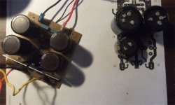
Your right on that .... actually have 2 groups of 4 caps (below) -
NEED POWER Many big bridges and large rectifiers - Albany NY prime E-waste.
To "fry up" some new amps - A "uni-cap" PCB (below 2).
-Takes DO-xx /TO-220 / or external bridge and can be snubbered.
- 10mm/2-pin and 22.5mm /4-pin pitch ... 25mm-42mm caps.
-starred / led / and bleeder capable.
- Up to 40Kuf with the 40mm units (slew-monster ready) !
UNI-CAP .lays and a bitmap for toner below in zip
PS - the "35mm snap-in .lay" is for jeff. Infidel will be working on mine first.
Time for me to give "the show".
Edit - wife has too many Xmas "chores" for me at times.
OS
NEED POWER
Many big bridges and large rectifiers - Albany NY prime E-waste.To "fry up" some new amps - A "uni-cap" PCB (below 2).
-Takes DO-xx /TO-220 / or external bridge and can be snubbered.
- 10mm/2-pin and 22.5mm /4-pin pitch ... 25mm-42mm caps.
-starred / led / and bleeder capable.
- Up to 40Kuf with the 40mm units (slew-monster ready) !
UNI-CAP .lays and a bitmap for toner below in zip
PS - the "35mm snap-in .lay" is for jeff. Infidel will be working on mine first.
Time for me to give "the show".
Edit - wife has too many Xmas "chores" for me at times.
OS
Attachments
On the Kypton-C input, I'm testing in 42 volt rails with 3.9K resistors in R18 and R19. I'm only getting 11.8 volts at the input side of R18 and R19. I'm trying to adjust the pot but the voltage never quite settles and is a little high. Do I need lower resistance values for R18 and R 19?
35-42V rails = 1.8K-2.2K , On the "C" you are not only running the first stage CCS - but the servo , as well.
On some amps (cfa-x) just the CCS is using the regulated supply. 3.9K is good here for lower rail voltages.
I simulated , it took 1.8K (14ma) to get a rock solid 12.25V on the zeners @ 40v rails. 2.2K gave 12.1V /11ma.
This is what most of my IPS's normally do at 60-75V rails (3.9-4.7K).
Edit - I plan on jury rigging 2 more 4.7K's on to my spooks zener circuit to get my 12ma+ , for
"bench testing". PS - the pot will not affect zener voltage , just trim the red led bias of the second stage. (VAS I)
OS
Last edited:
Infidel is a (you know what)  ....
....
But I love it.
Thermally , Q1/5 - 2/7 - 4/6 - and 3/8 .... are the ones that directly cancel
(T/ beta). All are now the same Vce - so this has to work.
I added the "anal" ability to thermally connect the whole TIS to 1- "U" shaped
heatsink across the 2 groups (of 2 pairs).
We don't need the inverting side thermally equalizing the non-inverting group of 4.
Any imbalance here would be corrected by feedback .
If any group of 2 was to increase in temp , it's gain would be the same (direct 2
device cancellation).The way to test this would be to touch any group of 2-
read offset and VAS I.
I left it "open ended" (any technique) to cover my ar$e.
OS
....But I love it.
Thermally , Q1/5 - 2/7 - 4/6 - and 3/8 .... are the ones that directly cancel
(T/ beta). All are now the same Vce - so this has to work.
I added the "anal" ability to thermally connect the whole TIS to 1- "U" shaped
heatsink across the 2 groups (of 2 pairs).
We don't need the inverting side thermally equalizing the non-inverting group of 4.
Any imbalance here would be corrected by feedback .
If any group of 2 was to increase in temp , it's gain would be the same (direct 2
device cancellation).The way to test this would be to touch any group of 2-
read offset and VAS I.
I left it "open ended" (any technique) to cover my ar$e.
OS
Attachments
Last edited:
It is not just changing the parts !! By having the diamonds face to face AND being
separate from the other "{face to face) "bridge" pairs , even if you made the
electrical changes the physical issues would still exist.
The tiniest temp. difference between the coupled diamond pair and the coupled bridge pair would be magnified on your board ....
even if you made the electrical changes.
In the new layout , ONE HALF of each diamond with its "bridge partner" is paired.
Opposite thermal effect of the last layout.
This IPS is very different than the others. wait ....
OS
separate from the other "{face to face) "bridge" pairs , even if you made the
electrical changes the physical issues would still exist.
The tiniest temp. difference between the coupled diamond pair and the coupled bridge pair would be magnified on your board ....
even if you made the electrical changes.
In the new layout , ONE HALF of each diamond with its "bridge partner" is paired.
Opposite thermal effect of the last layout.
This IPS is very different than the others.
wait ....OS
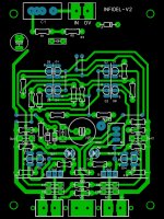
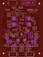
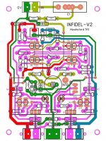
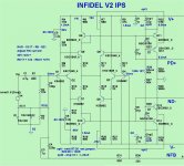
Infidel-V2
Here it it ....
-Schema with 40V and 70+ V notes (below 1).
- Layout with verbose voltage guide (below 2).
Physics of the P/N devices says it HAS to be thermally stable.
Package attached.
OS
Here it it ....
-Schema with 40V and 70+ V notes (below 1).
- Layout with verbose voltage guide (below 2).
Physics of the P/N devices says it HAS to be thermally stable.
Package attached.
OS
Attachments
All 4 pairs just plain "face to face" = great performance.
All 4 pairs with thermal epoxy and a copper/aluminum plate across them all =
"anal / lab" performance.
Simulated individual bridge/diamond pairs (like Q1/5) swept independently ,
less than .05ma ... 0-50C . Global 0-50C (all devices swept) is at the uA level -
thermally. Individual actual beta's of the devices might degrade this ,
but natively it is better than the spooky by a wide margin.
PS - I won't step in "poo" twice .
OS
All 4 pairs with thermal epoxy and a copper/aluminum plate across them all =
"anal / lab" performance.
Simulated individual bridge/diamond pairs (like Q1/5) swept independently ,
less than .05ma ... 0-50C . Global 0-50C (all devices swept) is at the uA level -
thermally. Individual actual beta's of the devices might degrade this ,
but natively it is better than the spooky by a wide margin.
PS - I won't step in "poo" twice
.OS
I could fit it on a 76 X 35mm card - "mini infidel" , using these ...
http://www.centralsemi.com/pdfs/products/pa_dual_sot228.pdf
- true 2% complimentary bjt's on one die.
OS
http://www.centralsemi.com/pdfs/products/pa_dual_sot228.pdf
- true 2% complimentary bjt's on one die.
OS
Did you have a 4 pin cap in mind for the uni-cap supply? My pinout is a little different for them. The two stabilizer pins are a little off.Your right on that .... actually have 2 groups of 4 caps (below) -
NEED POWER
To "fry up" some new amps - A "uni-cap" PCB (below 2).
-Takes DO-xx /TO-220 / or external bridge and can be snubbered.
- 10mm/2-pin and 22.5mm /4-pin pitch ... 25mm-42mm caps.
-starred / led / and bleeder capable.
- Up to 40Kuf with the 40mm units (slew-monster ready) !
UNI-CAP .lays and a bitmap for toner below in zip
PS - the "35mm snap-in .lay" is for jeff. Infidel will be working on mine first.
Time for me to give "the show".
Edit - wife has too many Xmas "chores" for me at times.
OS
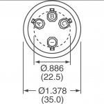
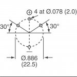
Did you have a 4 pin cap in mind for the uni-cap supply? My pinout is a little different for them. The two stabilizer pins are a little off.
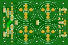
I used my standard sanwha 8200/100v's to "get it close" . I DID NOT use the
30 degree radius spacing for these. I've made several boards with this spacing -
and your right - not EXACT.
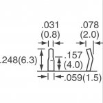
Feel free to to get those pins perfect (4 pin). Below are the exact panasonic 4 pin
35-42mm cap spacings - the 3'rd pix is the actual terminal (2mm - got that right).
OS
Attachments
- Home
- Amplifiers
- Solid State
- Slewmaster - CFA vs. VFA "Rumble"