There are two technical errors in Rod Elliott's circuit diagram shown in post 1. You implemented these in good faith but they are holding you back. That is the reason I recommended cutting that yellow wire and fixing that to the chassis near the supply capacitors.
Do you mean the green/yellow wire that earths the power supply to the chassis?
Are you suggesting that this should be connected to the chassis say 2 inches from the output of the power supply rather than at the earth point beside the IEC socket?
Are you suggesting that this should be connected to the chassis say 2 inches from the output of the power supply rather than at the earth point beside the IEC socket?
Yes, it is a starting point but see amplitudes wiring bible. It is the one I have used in the past. I suggest to simplify matters that you use the 15-0-15 secondary windings to power your ancillary circuits.Do you mean the green/yellow wire that earths the power supply to the chassis?
Are you suggesting that this should be connected to the chassis say 2 inches from the output of the power supply rather than at the earth point beside the IEC socket?
If it were mine I also try and flip the heatsink 180 degrees, so that it also acts as shielding.
The symbol Rod Elliott used is for domestic electrical safety against electrocution. This differs from the one used in LT Spice which concerns electronics a distinctly different field.Great guide. And addresses one of the areas that causes the most confusion - grounding issues.
I have a quick question, I'm having trouble with fitting my crc in the chassis, and found a couple of nice jlh ripple eaters I build years ago, you guys have experience with ripple eaters and class ab amps?
Sorry for threadjacking.
Sorry for threadjacking.
Give it a try, I was wandering what is your ideling current? I read somewhere that to low ideling current could cause instability
G'day Guys,
I finally had an evening free to run some more tests.
First up was a series of tests on a Pioneer VSX915.
Volume dial set to 0, direct mode.
Some rather interesting results:
4R load
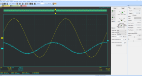
1khz sine

1khz square
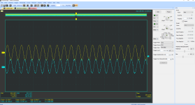
10khz sine
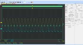
10khz square
4R + 150nF
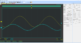
1khz sine
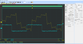
1khz square
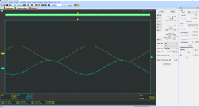
10khz sine
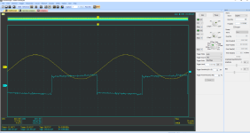
10khz square
I don't entirely understand what I am seeing here.
1khz square wave looks terrible.
10khz square waves are outputted as a sine wave
10khz sine wave is inverted
I also ran 4R with 470nF and 2.2uF.
Things were much the same.
I finally had an evening free to run some more tests.
First up was a series of tests on a Pioneer VSX915.
Volume dial set to 0, direct mode.
Some rather interesting results:
4R load

1khz sine

1khz square

10khz sine

10khz square
4R + 150nF

1khz sine

1khz square

10khz sine

10khz square
I don't entirely understand what I am seeing here.
1khz square wave looks terrible.
10khz square waves are outputted as a sine wave
10khz sine wave is inverted
I also ran 4R with 470nF and 2.2uF.
Things were much the same.
There are a few possible explanations, however I have no idea how you got that 1Khz square wave output!
One thing to note is that the EMI protection will limit the harmonic content of the 10Khz square wave since there are only odd harmonics, the first of which is at 30Khz which is outside the audio band. Injecting your signal after the EMI protection might alter this a bit, but perfect 10Khz square wave output signals are perhaps more designer machismo rather than a Hi Fidelity requirement. That said, if the amp has high bandwidth it will do a better job eliminating harmonics with NFB.
The phase inversion at 10K is probably just phase shift and may again be an artifact of aggressive EMI protection.
I’m not familiar with that model of amp. If it is an integrated amp with a preamp section, then that will have an effect. Your mention of direct mode suggests that it has a preamp/signal processor in it.
Amps with an inadequate slew rate will also round off square waves.
There is however no ringing or signs of oscillation which is good. If this amp is Class D that might go a long way to explaining some of this as the output filters will have a significant effect and the input processing will struggle with the fast rise times on a 10Khz square wave.
Not sure if I’ve been much help on this one 😊!
EDIT: I just checked online, this would appear to be class D as the heatsinks inside look much too small for class B or AB for an amp of that power. Distortion specs are also a bit higher than you get for Class B or AB.
Last edited:
My guess was that something in the input/ source selection part of the amp is not allowing a square wave through.
Direct mode would in theory bypass the signal processing but I would imagine it is more a case of not applying processing rather than strictly bypassing.
I did notice that the 1khz sine wave is much cleaner on the pioneer than my P3A which to me implies the issue is with the P3A rather than the test rig.
I have another sig gen on order to see if this changes things at all.
I will see if I can figure out how to run a frequency sweep when I get on this evening.
Last night I also tried putting a lid on my test case to see if this changed the measurements of my P3A at all via better shielding.
It didn't change anything so assuming i can rule out issues of my testing rig soon, I think I will have to start adjusting the P3A boards themselves.
My thoughts on priority would be:
1) change the 100pF at C2 to 220pF
2) try removing the cap across c-e on q9
3) adjust driver stage current
4) look at the feedback loop
The response of the 100pF filter is minus 3 dB at 1.59 MHz there are other reasons to use passive low pass filtering of the input signal like avoidance of slew rate limiting meaning a square wave cannot be reproduced properly which from the images of tests done up to date looks likely to be the case. The Vas needs to respond in adequate time - time having an inverse relationship with frequency.2.2nf would be a bit high. The impedance at 20KHz is about 3.6K so you would have low input impedance at high frequency as well as attenuated HF response due to the 1K series resistance.
100pf is to limit EMI ingress and you shouldn’t need much more than this.
If this amplifier is feed from a low source I would make c2=1nF. If the input is through a log pot that could be reduced somewhat but that situation is unclear. The tests appear to have been from a low impedance signal generator. If the NJW output devices or other equivalents with 30 MHz unity gain capability are used then C5 could be reduced to 68pf. These moves are contingent on changes to component values in a simulation which gives 0.02% THD at 20kHz into 8 Ohms at 30Volts peak. These are
1. replace BD140 at Q4 with KSA1381.
2.Delete capacitor C6 which makes no difference in the revised circuit whether in or out.
3. Reduce R12 and R11 to 100 Ohms
4. Include a series output resistor of 0.22 Ohms - this could eventually be replaced by a damped output coil but in the meantime it provides isolation from capacitor loads.
5. Make R15 8 Ohms.
6. Bridge Q9 collector to emitter with 220n capacitor. Replace the Vbe multiplier with BD139 to be mounted on same heat sink at output devices which operate at powers up to 50Watts whereas the drivers run at the 1Watt level more less constantly.
The details are shown in the attachment. As far as the vbe circuit goes all examples of CFP amplifiers in the Motorola Application Note AN484 are concerned there was a special two diode device used for that purpose.
I think a BC556B transistor would have been a better choice from commonly available devices than BD140 for Q4. The former has a more regular FFT profile if one is into this level of detail and slightly less THD
I can supply images for tests I have undertaken in simulations and an .asc file for anyone interested.
Attachments
- Home
- Amplifiers
- Solid State
- Stability testing my new Rod Elliot P3A
