I like the approach to fault finding. Unfortunately on the scope tests these are not on a par with yours in post 1. so we are back at square one. In post 2 Kramtweeter suggested there is a problem with the low pass filter. This ended up going nowhere as a second party suggested this was not a problem in his hardware. A third party asked the latter if he had built the amplifier, which was the case and how it performed on 10kHz square wave input. To this, the answer was"good". You could accept this if images of his scope tests had been provided, others less this pass without comment, possibly out of politeness, but you accepted this in good faith.
Last edited:
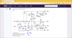
Mine too it allows frequencies above the time it takes to charge and discharge Q4 collector capacitance where C4 value is magnified it is within the feedback path of common emitter amplifier. With the limited the half share of LTP current reaching Q4 base in time to complete a full cycle is something to leave to chance.That input filter is totally inadequate in my view. You could try increasing C2 to 470pF or even 1nF.
Some people are not aware that frequency has an inverse relationship with time. I would go for 1nF in this instance and connect C4 not to the base of Q4 but to base Q2. That would avoid amplifying C4 and the small signal voltage section feedback would bypass the output stage at high frequencies.
I have seen this approach in amplifiers due to Linsley-Hood and Nelson Pass. Self uses a buffer transistor ahead of the common emitter transistor. The buffer transistor collector connects to earth - zero volts which is where the collector capacitance will disappear.
Last edited:
1.1k load is to high, dont you have any Below 100r, doesn't have to be power resistors, just mind the volume knob.
I set bias on mine yesterday too, I tagged wire onto the outputs, series emitters, to risky with probes while adjusting trimmer and watching meters, tagged wires are safe.
Ps mine behave very well, set at 75ma, very stable.
Cross my fingers for you sadface.
I set bias on mine yesterday too, I tagged wire onto the outputs, series emitters, to risky with probes while adjusting trimmer and watching meters, tagged wires are safe.
Ps mine behave very well, set at 75ma, very stable.
Cross my fingers for you sadface.
Attachments
OK.
1) Grounding the probe on the negative speaker jack seems to have cleaned up the measurements a lot.
2) I twisted 2x270R and 1x 220R 5w wirewounds together to make a 83.4R 15W resistor.
3) I seem to have a rather noisy measurement setup: Cheap scope, cheap scope probes, ladder type stepped attenuator to get the sig gen down to a useful level, alligator test leads to hook up the various parts.
4) My power rails are decently clean: 300mV ripple with no signal.
Left side 1KHz sine wave

Left side 10KHz sine wave

Left side 1KHz square wave

Left side 10KHz square wave

Right side 1KHz sine wave

Right side 10KHz sine wave

Right side 1KHz square wave

Right side 10KHz square wave

So this all looks pretty good to me. Noisy, but decent.
I don't see any obvious oscillation.
It looks to me like I am OK to hook up a 4R load for further stress testing.
It could be interesting to beef up the input filter as suggested to see if I can chop down the noise
1) Grounding the probe on the negative speaker jack seems to have cleaned up the measurements a lot.
2) I twisted 2x270R and 1x 220R 5w wirewounds together to make a 83.4R 15W resistor.
3) I seem to have a rather noisy measurement setup: Cheap scope, cheap scope probes, ladder type stepped attenuator to get the sig gen down to a useful level, alligator test leads to hook up the various parts.
4) My power rails are decently clean: 300mV ripple with no signal.
Left side 1KHz sine wave
Left side 10KHz sine wave
Left side 1KHz square wave
Left side 10KHz square wave
Right side 1KHz sine wave
Right side 10KHz sine wave
Right side 1KHz square wave
Right side 10KHz square wave
So this all looks pretty good to me. Noisy, but decent.
I don't see any obvious oscillation.
It looks to me like I am OK to hook up a 4R load for further stress testing.
It could be interesting to beef up the input filter as suggested to see if I can chop down the noise
I note the power supply wiring is not twisted as it should be to keep out radiated fields due to diode bridge switching. One thing that is missing in Rod Elliott's circuit in post1 is a 10R resistor to ensure the clean ground has a degree of isolation so this not contaminated by the dirty one. You don't want dirt switching from the supply traveling through a section of clean ground wiring. The 10R should be the last Earth connection on a wire chain to earth. This may be the case on Rod Elliott's pcb but it appears you are using one that you made.OK.
1) Grounding the probe on the negative speaker jack seems to have cleaned up the measurements a lot.
2) I twisted 2x270R and 1x 220R 5w wirewounds together to make a 83.4R 15W resistor.
3) I seem to have a rather noisy measurement setup: Cheap scope, cheap scope probes, ladder type stepped attenuator to get the sig gen down to a useful level, alligator test leads to hook up the various parts.
4) My power rails are decently clean: 300mV ripple with no signal.
Left side 1KHz sine wave
View attachment 1225878
Left side 10KHz sine wave
View attachment 1225880
Left side 1KHz square wave
View attachment 1225879
Left side 10KHz square wave
View attachment 1225881
Right side 1KHz sine wave
View attachment 1225882
Right side 10KHz sine wave
View attachment 1225885
Right side 1KHz square wave
View attachment 1225884
Right side 10KHz square wave
View attachment 1225883
So this all looks pretty good to me. Noisy, but decent.
I don't see any obvious oscillation.
It looks to me like I am OK to hook up a 4R load for further stress testing.
It could be interesting to beef up the input filter as suggested to see if I can chop down the noise
Attachments
Last edited:
Your pcb does not look like the board shown in post 12. It seems have added extra capacitors to power the small signal stages. If these supplies use the same bridge rectifier as the rest of each amplifier you will have more than one earth T point for each of these. The currents flowing between opposite ends of the capacitors for the small signal stage are close to the input the large currents that flow between these opposite ends will radiate fields into the front end of your amplifiers due to the proximity to the input. This modification is getting in the way of trouble shooting to find a fault. You went back to Rod's pcb for a reset but then made embellishments which have not helped - compare the latest scope results with your first batch of tests.I'm using Rods board right now.
Rods board does not have a 10R ground lift.
All my power supply wiring is twisted, both ac to the rectifiers and dc from psu board to amp boards.
With regard to a low pass input filter the present arrangement will fall short with a low output impedance source. However there is a question where the volume control should be sited. You could get some frequency roll off response effect with a dual 20k or 50k log pot at your input. That may have been what Rod Elliott had in mind.
The board in post 12 is not of Rod's design. That is something else from goodness knows where.
So far I have only been using Rod's board.

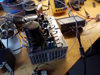
An old photo, I have since tidied up the wiring a tad but this is merely a test rig for proof of concept before implementation in the proper chassis.

So far I have only been using Rod's board.
An old photo, I have since tidied up the wiring a tad but this is merely a test rig for proof of concept before implementation in the proper chassis.
Looks tidy however the input looks very close to your output terminals. That is a no no thing as the input can pick up radiated fields if this is too close. This could account for the fuzz/noise in your 'scope traces. The input wire should also be of the shielded type with the shield connected to the earth of the phono jack.
Last edited:
G'day guys,
Another round of testing this evening: same tests on a 4R load.
I seem to have a noisy square wave this evening.


This is just the output of the sig gen unconnected to the amplifier
Left channel 1kHz sine wave

Left channel 1kHz square wave

Left channel 10kHz sine wave

Left channel 10kHz square wave

Right channel 1kHz sine wave

Right channel 1kHz square wave

Right Channel 10kHz sine wave

Right Channel 10kHz square wave

There's a bit of a ring on the square wave but this is seen on the input so I think it is just an artifact of my measurement setup.
This all looks pretty good to me.
I don't see any obvious signs of a break out into oscillation.
Another round of testing this evening: same tests on a 4R load.
I seem to have a noisy square wave this evening.
This is just the output of the sig gen unconnected to the amplifier
Left channel 1kHz sine wave
Left channel 1kHz square wave
Left channel 10kHz sine wave
Left channel 10kHz square wave
Right channel 1kHz sine wave
Right channel 1kHz square wave
Right Channel 10kHz sine wave
Right Channel 10kHz square wave
There's a bit of a ring on the square wave but this is seen on the input so I think it is just an artifact of my measurement setup.
This all looks pretty good to me.
I don't see any obvious signs of a break out into oscillation.
I had a second look at the image in post 310 with respect to the power supply. It appears that your transformer has two secondary windings for the power amp section and a second set for a low power amplifier. I don't know where you got the pcb for the capacitors from - I didn't see this on Rod Elliott's pages.G'day guys,
Another round of testing this evening: same tests on a 4R load.
I seem to have a noisy square wave this evening.
View attachment 1226223
View attachment 1226224
This is just the output of the sig gen unconnected to the amplifier
Left channel 1kHz sine wave
View attachment 1226225
Left channel 1kHz square wave
View attachment 1226226
Left channel 10kHz sine wave
View attachment 1226227
Left channel 10kHz square wave
View attachment 1226228
Right channel 1kHz sine wave
View attachment 1226229
Right channel 1kHz square wave
View attachment 1226230
Right Channel 10kHz sine wave
View attachment 1226231
Right Channel 10kHz square wave
View attachment 1226232
There's a bit of a ring on the square wave but this is seen on the input so I think it is just an artifact of my measurement setup.
This all looks pretty good to me.
I don't see any obvious signs of a break out into oscillation.
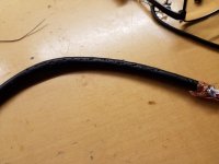
It appears you have rectified the main secondary windings separately to charge capacitors for each amplifier module. There is a skimpy black lead which appears to be from the low power set of windings that has been used as an earth which would be inadequate given the current involved with the main secondaries. I hope I am not just seeing things but where is the earth point for the main secondary section.

I haven't measured the output of many psus before but I would have thought this was quite reasonable for a class AB amp.Unsure about p3a pssr ,Could the high ripple be causing problems? 300mv with no signal, I wonder how the rails modulate with signal and load.
There is 2x 15000uF per rail. All of the faulty home theatre amps I salvage bits from typically have less than 10000uF per rail for a 5-7 x 100w per channel amplifier.
P9-P13 whatever these may represent are in the dirty earth path so these points will be contaminated by artifacts of C1-C4 charging currents of these large capacitances will be very great. There are 5 chances one of these could be critical especially if they are in the voltage gain part of the amplifiers.The psu is my own creation.
View attachment 1226466
Both channels run off the 1 psu.
2x 24vac secondaries feed dual bridges.
The unused secondary is 15-0-15 which is rolled up, heatshrinked and cable tied out of the way.
If so the immediate solution would be to cut the yellow wire an inch or so before it reaches the screw down bracket. Then strip the wire and crimp an eyelet to the end and screw that to the chassis. So far you have not tried any solutions I have suggested but there is nothing hard about trying this one.
If I put my bench magnifier lamp that uses a CFL anywhere near my amp under test, it makes a horrible mess of my nice clean traces.
It may be some electrically noisy device plugged in nearby affecting your amp.
I sometimes use a battery powered oscillator so I can be sure I’m not getting noise injected via a noisy ground somewhere.
Hope that helps!
It may be some electrically noisy device plugged in nearby affecting your amp.
I sometimes use a battery powered oscillator so I can be sure I’m not getting noise injected via a noisy ground somewhere.
Hope that helps!

- Home
- Amplifiers
- Solid State
- Stability testing my new Rod Elliot P3A