Similar observation to Grauwacke post 54The unwanted signal superimposed on the output seems to be about 68 kHz. Maybe that'll give you some ideas?
The only thing that I can think of that would run at such a frequency would be a switchmode power supply?The unwanted signal superimposed on the output seems to be about 68 kHz. Maybe that'll give you some ideas?
There is of course 2 lcd screens running on the same mains circuit as the computer, which surely use smps.
Or perhaps some noise from the computer itself?
Are your traces any different to Sadfaces ones?Have same issue with my two led lights, they turn up on oscilloscope traces.
So I did some further testing last night.
Both channels look stable to me on the 4R load that proved to be the demise of my first P3A attempt.
So i started adding some capacitance in parallel with the 4R load.
Both channels behave the same so I won't bother posting both channels. This is 4R + 3.3nF

1kHz sine wave

1kHz square wave

10kHz sine wave

10kHz square wave.
Whilst there is quite a ring at the output visible on the square waves, it is visible on channel 2 at the input so I don't think this is the output stage ringing but merely reproducing what is at its input.
I think went to 4R + 150nF and got this.

1kHz sine wave

1kHz square wave

10kHz sine wave

10kHz square wave.
I noticed that on the really bad looking traces at 1kHz. The input and output voltages have a 27db difference which is exactly the expected gain of the amp.
If the output were oscillating I would think I would see a larger signal at the output. I saw this on the first attempt that clearly was oscillating back in post 1.
So if I am not missing something here, it looks to me like something is interfering heavily before the input of the amp and the amp is merely doing its job of amplifying the terrible signal at its input.
Both channels look stable to me on the 4R load that proved to be the demise of my first P3A attempt.
So i started adding some capacitance in parallel with the 4R load.
Both channels behave the same so I won't bother posting both channels. This is 4R + 3.3nF
1kHz sine wave
1kHz square wave
10kHz sine wave
10kHz square wave.
Whilst there is quite a ring at the output visible on the square waves, it is visible on channel 2 at the input so I don't think this is the output stage ringing but merely reproducing what is at its input.
I think went to 4R + 150nF and got this.
1kHz sine wave
1kHz square wave
10kHz sine wave
10kHz square wave.
I noticed that on the really bad looking traces at 1kHz. The input and output voltages have a 27db difference which is exactly the expected gain of the amp.
If the output were oscillating I would think I would see a larger signal at the output. I saw this on the first attempt that clearly was oscillating back in post 1.
So if I am not missing something here, it looks to me like something is interfering heavily before the input of the amp and the amp is merely doing its job of amplifying the terrible signal at its input.

So far no likes, I don't share your optimism.So I did some further testing last night.
Both channels look stable to me on the 4R load that proved to be the demise of my first P3A attempt.
So i started adding some capacitance in parallel with the 4R load.
Both channels behave the same so I won't bother posting both channels. This is 4R + 3.3nF
View attachment 1226589
1kHz sine wave
View attachment 1226591
1kHz square wave
View attachment 1226592
10kHz sine wave
View attachment 1226593
10kHz square wave.
Whilst there is quite a ring at the output visible on the square waves, it is visible on channel 2 at the input so I don't think this is the output stage ringing but merely reproducing what is at its input.
I think went to 4R + 150nF and got this.
View attachment 1226606
1kHz sine wave
View attachment 1226607
1kHz square wave
View attachment 1226608
10kHz sine wave
View attachment 1226609
10kHz square wave.
I noticed that on the really bad looking traces at 1kHz. The input and output voltages have a 27db difference which is exactly the expected gain of the amp.
If the output were oscillating I would think I would see a larger signal at the output. I saw this on the first attempt that clearly was oscillating back in post 1.
So if I am not missing something here, it looks to me like something is interfering heavily before the input of the amp and the amp is merely doing its job of amplifying the terrible signal at its input.
If you have another amplifier you could have something objective for comparison to see whether the problem is due to your test equipment or this amplifier. The 4R +150nF images look like abstract art. It is hard to see your test equipment is the artist.
Last edited:
It would be interesting to know the identity of your transistor selections.Mjona, in mv region they appear on traces less than sadface, but there, but now, whenever I measure, I turn off all unnecessary equipment and light
Yesterday I did post some square wave measurements over in p3a long thread.
With respect to my comment in post 323 about noise being induced in an amplifier by a workplace computer. The amplifier in question had a low pass filter but that did nothing to keep the noise out. It was necessary therefore to add a second low pass filter where from memory the capacitor for this was a silver mica type. This information was contained in an issue of Hifi and Record Review in relation to an Audiolab amplifier. I have found that a small ferrite bead works well enough at the input - the insulated signal wire can be thread through the hole in the bead. I used to get noise from fluorescent lighting before taking this step.
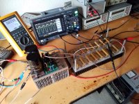
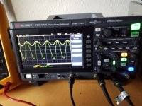
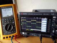
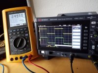
I did the 4 ohm with 150nf across load, it was quick and dirty, took it all apart yesterday, testing done, so this setup is powered by two switch supplies, and the 20000uf.
Looks clean enough.
3 first 1khz, last 10khz
Looks clean enough.
3 first 1khz, last 10khz
Attachments
Last edited:
- Home
- Amplifiers
- Solid State
- Stability testing my new Rod Elliot P3A