Member
Joined 2009
Paid Member
People might have difficulty to judge which ones are good amps, average amps, or great amps using ears alone. But when they have a system and they experience enjoyment in using it, they will remember the system and keep it.
Many people these days do not have access to a hi-end audio showroom to go and listen. There are fewer bricks and mortar stores everyday as e-commerce becomes the more convenient and cheaper option for buying goods. In rapidly developing countries this is even more the case. People will buy based on word of mouth and reviews, like the 'star rating' system on amazon etc. When people are buying hi-fi without hearing it they are not going to choose something off-brand. Hence we see the popularity of portable music players and downloadable music because a lot of people can be easily exposed to this technology worldwide without having to search out a store to hear it. It's not just the convenience of music downloads therefore, it's the convenience and low-risk choice for buying the reproduction equipment that drives the move to Class D because it's portable and ubiquitous. You can desire people to want to explore the nuances of carefully voiced Class AB but I don't see this happening anytime soon.
I do wonder if it isn't the case that the new rich want bling more than sound.
Last edited:
I always remeber in 1973 stopping off in Winchester to warm up after a motorbike ride and entered my first real hi fi shop of the type I think people mean here. The guy was so helpful, I wanted to buy the Celestion 66's just to please him. I forgot my visit to Horn's in Oxford and the super nice Phil Tandy talking about frequency doubling in speakers ( 1970, I was 14 ). I had just said I was only dreaming to buy one day. He seemed so much more interested to talk when I said that. What a really nice man and a real educator. Witney Audio in Oxfordshire was where I bought my parts. Again super professional guys. I bought my first real hi fi from G W Smith Ltd. They were very good people also in Paddington Green ( 1970 again ).
Member
Joined 2009
Paid Member
After the earlier discussion on polarity, it would be correct to place them in reverse polarity to that used by Naim, which has been conventional, i.e. -ve to ground, on every original example I've seen and of course, these were always tantalum caps - though not with the majority of kit clones. You may notice that Avondale dropped the correct polarity for the FB cap. in later NCC200 versions, AFAIK....The polarity of the input and feedback shunt capacitors confuse me a little ?
So, do you go original and technically wrong or go right but unconventional. That's your call but if you are looking to identify and compare sound quality, it makes sense to at least start out as original. How hard is it to then reverse them and assess whether it matters?
An externally hosted image should be here but it was not working when we last tested it.
Last edited:
Member
Joined 2009
Paid Member
Interesting, didn't realize that Naim had them 'wrong', I thought it was just Avondale. My worry is not to risk reliability and damage to the caps by reverse biassing them - Tantalum caps are known to be highly allergic to reverse bias. However, from reading some studies on-line, including one from nasa, the input cap and fdbk cap are both in high-impedance circuits where there isn't enough current to cause failure. And although increased leakage current could be expected the caps will likely be stable for a long time unless current levels were higher. If it's safe to copy the original Naim, that would be my preference. Currently, my pcb is inconsistent, I think the input cap has the opposite sign to the base of the LTP transistor than the feedback shunt cap.
It's a pitty, but I can't see from the photos of real Naim amps what orientation the caps have been installed. Not saying your information is wrong but it'd be nice to see it in the daylight so to speak.
It's a pitty, but I can't see from the photos of real Naim amps what orientation the caps have been installed. Not saying your information is wrong but it'd be nice to see it in the daylight so to speak.
Last edited:
FWIW, many others are still confused too. The information in this PFM thread is still contradictory since the designer, Les Wolstenhome, is quoted as using the correct polarity, admitting at least some his own schematics have been wrong. However, if you reconcile the small detail pic of one of his bare PCBs in that thread with pics of modules from his brochure, he's even wrong about his own product because the 68uF wet tantalum caps's case is connected to 0V on the built modules shown.
Yes, when flicking through the hundreds of pics of original NAP models going back to the 1970s on the web, I notice that many have off-brand parts fitted and obviously DIY refurbs rather than original. It won't be a simple matter of believing what you see since they may have been oriented either way at that time. So, do we use our eyes or accept the the rhetoric?

NCC200 Power Amplifier Module Brochure | AVONDALE AUDIO
'Just checked a more recent Naim design NAP200 board I have. This is a "drop in" copy and identical layout. It shows input cap is -ve to input transistor base and FB caps (2x47uF) are -ve to ground. Hmm...you can have all kinds
Yes, when flicking through the hundreds of pics of original NAP models going back to the 1970s on the web, I notice that many have off-brand parts fitted and obviously DIY refurbs rather than original. It won't be a simple matter of believing what you see since they may have been oriented either way at that time. So, do we use our eyes or accept the the rhetoric?
NCC200 Power Amplifier Module Brochure | AVONDALE AUDIO
'Just checked a more recent Naim design NAP200 board I have. This is a "drop in" copy and identical layout. It shows input cap is -ve to input transistor base and FB caps (2x47uF) are -ve to ground. Hmm...you can have all kinds
Last edited:
Interesting, didn't realize that Naim had them 'wrong'
What do you mean? The LTP bases are negative. But even if you put the positive poles towards LTP bases (like normally found in schematics), the cap IME will survive.
Positive towards gnd.It's a pitty, but I can't see from the photos of real Naim amps what orientation the caps have been installed.
Upside-down caps for the Australian market?

No.
I would recommend using a temporary non-polar or electrolytic during turn-on in case there is a fault that drives the output to the positive rail.
Last edited:
This makes interesting reading. I would never have tought them this fragile!
I think there is a rule of thumb that says Tants should never be reverse biased by more than 15% in these situations. OS CON are better. The 15% assumes micro amps.
Power on and off procedure...... | Naim Audio Forums
Very cheap non polar caps have a good reputation if saying distortion. If the Naim preamps were configured for +/- 12 V the input base could sit close to 0V +/- 100 mV. When I design power amps I often prefer to have a 500 mV input sensetivity so as to best exploit non polar caps and suit CD directly fed in via a pot. The very worst thing you can do is polarise a capacitor if there was a way to avoid it. Even polar types.
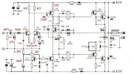
I couldn't find my 2 pole Cdom 100 watt amp. I did find this. If the 2 pole is made one pole 50 kHz shows some distortion which Complimentary Feedback Pairs do not. It makes the FET's and Cmfbp about equal. This is not a good design, it's just a bit of fun and out performed a OPA 604 with Cfbp buffer. If it had been run on the AP test station I would think distortion would be in the better op amp levels. Notice all the hard problems are addressed. The 4 x 1000 uF output caps were for safety. The DC offset was always close to this value. I would have liked the feedback arm cap to be at a lower DC value. Alas that's the best I came up with. I never intended this to be shown here so please forgive the format. The Naim could be made to work this way. Personally I would prefer this over the Cmfbp input that some get excited by.
Note also slewing would be OK although typical assymetry. 47R purple was reduced to 16R. As it is an overbiased class AB very high loop gain is not the most important thing.

I think there is a rule of thumb that says Tants should never be reverse biased by more than 15% in these situations. OS CON are better. The 15% assumes micro amps.
Power on and off procedure...... | Naim Audio Forums
Very cheap non polar caps have a good reputation if saying distortion. If the Naim preamps were configured for +/- 12 V the input base could sit close to 0V +/- 100 mV. When I design power amps I often prefer to have a 500 mV input sensetivity so as to best exploit non polar caps and suit CD directly fed in via a pot. The very worst thing you can do is polarise a capacitor if there was a way to avoid it. Even polar types.
I couldn't find my 2 pole Cdom 100 watt amp. I did find this. If the 2 pole is made one pole 50 kHz shows some distortion which Complimentary Feedback Pairs do not. It makes the FET's and Cmfbp about equal. This is not a good design, it's just a bit of fun and out performed a OPA 604 with Cfbp buffer. If it had been run on the AP test station I would think distortion would be in the better op amp levels. Notice all the hard problems are addressed. The 4 x 1000 uF output caps were for safety. The DC offset was always close to this value. I would have liked the feedback arm cap to be at a lower DC value. Alas that's the best I came up with. I never intended this to be shown here so please forgive the format. The Naim could be made to work this way. Personally I would prefer this over the Cmfbp input that some get excited by.
Note also slewing would be OK although typical assymetry. 47R purple was reduced to 16R. As it is an overbiased class AB very high loop gain is not the most important thing.
Funny thing that I never saw at the time. The feedback cap could be biased with a diode to it's other side. It could have a nett 0V for pennies. I said all caps shouldn't be biased. Obviously polyester can be. Even so some have memory effects and 63V polyester is not well liked.
https://linearaudio.nl/cyril-batemans-capacitor-sound-articles
If you look the distortion at 50 kHz is higher when purple resistor is 0R. This isn't the improvement of local feedback is my guess. It is the onset of nasty sound due to Cdom. Food for thought. Notice also the VAS input current is generous at double the Naim. The gain of the BC547C is double that of the Naim or higher.
My home brew Wien Bridge is about - 68 dB at 50 kHz ( NE5532 + RA53 ). There is every chance this amp is at - 80 dB. Personally if I get to - 60 dB 50 kHz at all power levels the job is done. If you look the 0R 50 kHz has spikes. That is the bigger deal, a no-no. I had hundreds of similar graphs. Christopher Pearson aged 33 got rid of them. I have a Wien I bought that says it's - 127 dB. I must get it in a box.
Some of the noise you see is me forgetting to switch off my Ethernet via mains. As it wasn't for showing here it wouldn't have bothered me at the time. This was a road trip and the destination was far up the road. The final version had a voltage multiplier +/- PSU and regualtor to the VAS. The ripple of the multiplier was horrid. The regulator was silent. Here it is simple RC.
I think I got the VAS caps down to 33+33 pF and a 3 dB improvement. I don't have the graphs. I thought I would get smoke at any moment as the rats nest grew. I didn't !
Last edited:
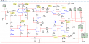
These version was modified by GB..
Any opinion..
It looks to be OK. The 1K5 1K5 is about right also. If we say circa 1V 1K5 that's about the same as before. Pure coincidence I put my silly JLH clone amp up. My guess is it will sound just like the other clones with better treble to use an old term.
These version was modified by GB..
Any opinion..
How do you like this amp, GB? Do you use the original transistors?
I would look at original 1K + 22K and 15 R to the VAS emitter. If you like that start adjusting the 1K to perhaps 1K3 and 30K. All guess work really. I have a hunch original Naim and 15R will do a bit. More of a risk is to add 1 uF to the 15R. As this amp has plenty of phase shifts goodness knows how that would go. It's mostly good book and good ear spec doing that, trying to satisfy both. It could end in smoke.
Member
Joined 2009
Paid Member
Positive towards gnd.
So, you are saying that the original NAP had the caps 'backwards' ?
I wonder what impact this has on the distortion profile for these caps, especially as they are in positions where the global feedback can not remove such distortion and it will therefore be audible if high enough.
I have never seen a NAP with the caps the wrong way around. I don't have one in front of me but all of the on-line photos of Naim-built boards that I have seen confirm it. Also, it makes no sense to me to reverse bias tantalum capacitors. They are, as you said, very delicate. In fact, they can become damaged (pitted) without actually failing and I believe enough subsequent forward bias can partially "heal" them. But if they get damaged it will be cumulatively bad for the sound and you may not even realize it.So, you are saying that the original NAP had the caps 'backwards' ?
I wonder what impact this has on the distortion profile for these caps, especially as they are in positions where the global feedback can not remove such distortion and it will therefore be audible if high enough.
Your question about distortion profile is a good one. If it were the case that particular tantalums will be unscathed with a hundred mV or so of reverse bias and a reverse bias improved their distortion characteristic for the particular design then ok. But I don't know because I have never knowingly reverse biased tantalums and I have not yet found a reason to try. In fact, the last time I reverse biased a tantalum it shot to the ceiling with a red flame and trail of smoke and then what remained of it wafted gently back to Earth and burned a hole in my sofa cushion. But that was many volts of reverse bias.

Last edited:
Member
Joined 2009
Paid Member
oh my gosh, a molten blob of burning tantalum on the sofa is not a good thing !
OK - so the recommendation is to install them the 'electrically correct' way around, meaning -Ve leg to the appropriate LTP base connection (+Ve to input/gnd). This means my pcb is mis-labelled for the feedback cap (no biggie).
OK - so the recommendation is to install them the 'electrically correct' way around, meaning -Ve leg to the appropriate LTP base connection (+Ve to input/gnd). This means my pcb is mis-labelled for the feedback cap (no biggie).
Greetings, Ruwe. The measurements were made by a computer program (RMAA), similar to Spectra Plus. It has an indication of the optimal input signal level to exclude the occurrence of clipping. Unfortunately, separately, the signal level was not measured. Thank you for noticing the phrase "load equivalent". In this case, it was just a resistor.That brings me to questions for Nikolai:
Nice to see some comparative measurements of a Naim clone.
I can't recognise what did your friend use for the harmonics measurements of the two amps. Is that a scope FFT?
I see the signal level is low at -3db. Why is that? Is there attenuation added at the measuring equipment inputs or you just tested at low power?
What do you mean by equivalent load? Do you mean you have built a standard load for testing amps which represents an average loudspeaker? If that's the case - very neat! I'm always considering of building one, but for now other stuff take priority.
Perhaps you are considering an option for the IHF A202 standard, or some other one. And, in principle, it would be very correct to do it. Because An attempt to remove the frequency response to acoustic systems, revealed the emergence of nonlinearity in the range from 100Hz to 350Hz, at a level of 0.4-0.5 dB.
On resistors - there is a straight line. Maybe this is a manifestation of the impedance of acoustic systems, and maybe something else .... We need to understand further.
Bigun, I'll give you more DC modes, which are shot in Multisim12 and a simulation file. Yes, and the capacitor 68mkF is better to include a "negative" - to the base of the transistor. Because I there really measured up to -100mV, without an input signal. Or use there BC128. I use, in this circuit, exactly two such capacitors.
Attachments
- Status
- This old topic is closed. If you want to reopen this topic, contact a moderator using the "Report Post" button.
- Home
- Amplifiers
- Solid State
- TGM10 - based on NAIM by Julian Vereker