I seize the opportunity to mention Kenpeter's version of the JLH: see below the small signal response.This circuit was first used by JLH back in the sixties as a phono amp and later as headphone amp with minor differences as youll be able to see from here.
The Class-A Amplifier Site - JLH Headphone Amplifiers.
Note that this is for the complete amplifier, loaded with its regular 8Ω, not just the front end.
And the output stage is based on humble 2N3055's.
The bandwidth is in excess of 20MHz.
Okay, it's the small signal response, and there is no way the 2N3055's could sustain a power bandwidth approaching that, but it shows the potential of the circuit.
Linearity is outstanding too.
I think it's the best thing since the original JLH. What do you think?
http://www.diyaudio.com/forums/solid-state/197707-shunt-regulated-jlh-3.html
Attachments

Hard to explain in English, for me.Could you elaborate on this, I am not sure I understand exactly what you mean?
Big transients (kick drums, as an example) heat the metal of the moving coils, increasing his impedance, and reducing efficiency, meeans acoustic level.
It is not the long time average temp of the all mobile coil assembly itself, but the short temperature delta from the metal in the coil and his capton/aluminium support. This phenomena brings non linear distortion LC refers as "thermal memory distortion". If the serial resistance in the CR is a metallic film one, and heat the same way, it reduce a little the phenomena: The film resistance will increase his impedance with heat, and, so, increase the overall gain of the amp dynamically.
This, of course you cannot measure with Harmonic analysis of a sinus wave, but you can ear as a little loss of dynamic and evaluate with a gain/power curve measurements.
Of course, this compensation will not be perfect, as the speed of thermal dissipation between the film and the support of the resistance will not be exactly the same than the one between the coil and his support. And the average temp of the both units not the same neither. But near is better than nothing.
Same behavior in the jonctions of power units, but CR can compensate it.
Member
Joined 2009
Paid Member
I think it's the best thing since the original JLH. What do you think?
I think it looks like a spot advert in the TGM5 thread for a completely different amplifier and project 😎
Elvee,
I agree with you. I have been doing a variant on KP's trick LTP since I saw it. Distortion profile is excellent.
However, this is Gareth's thread; KP's circuit maybe should be moved elsewhere.
Hugh
I agree with you. I have been doing a variant on KP's trick LTP since I saw it. Distortion profile is excellent.
However, this is Gareth's thread; KP's circuit maybe should be moved elsewhere.
Hugh
Last edited:
Member
Joined 2009
Paid Member

Not my fault if Homemodder started it 😀I think it looks like a spot advert in the TGM5 thread for a completely different amplifier and project 😎
OK, that's known and accepted, it is thermal compression.Hard to explain in English, for me.
Big transients (kick drums, as an example) heat the metal of the moving coils, increasing his impedance, and reducing efficiency, meeans acoustic level.
It is not the long time average temp of the all mobile coil assembly itself, but the short temperature delta from the metal in the coil and his capton/aluminium support. This phenomena brings non linear distortion LC refers as "thermal memory distortion".
No, it doesn't work that way: film resistors are made of alloys designed to have zero TC.If the serial resistance in the CR is a metallic film one, and heat the same way, it reduce a little the phenomena: The film resistance will increase his impedance with heat, and, so, increase the overall gain of the amp dynamically.
Depending on the quality, the care brought to the manufacturing, etc, the zero TC target will be achieved with more or less accuracy, and there are groups based on the tightness of the tolerance: 200ppm/°C, 100ppm/°C etc.
There is no sign in front of the TC, because the actual TC can be anywhere between the positive and negative max values.
If you use such a resistor for compensation purpose, you will get completely random results: if you are lucky, you will get some compensation, but if you are unlucky, the compensation could do nothing, or worst, aggravate the problem.
In such situations, the best strategy is to minimize the thermal effect, because you have no real control over it.
There are special compensating resistors, such as the +3000ppm/°C ones used to compensate for absolute temp in analogue computation circuits, but that's completely different.
To compensate for the voice coil temp, the best deterministic strategy is to use a thermal image compensation: you create a small copper resistance having homothetic thermal properties, self-heating and time constant.
You can then use the voltage generated to correct the feedback signal.
See an example here: http://www.diyaudio.com/forums/atta...487444-servo-sound-made-belgium-thermimg2.jpg
It can be measured by measuring the current instead of the voltageThis, of course you cannot measure with Harmonic analysis of a sinus wave, but you can ear as a little loss of dynamic and evaluate with a gain/power curve measurements.
You are right, just tried now, and some resistances i have can even have negative thermal curves in our amps temperature ranges. Happily, the ones i used for CR (thick film) had, when i first measured them with this idea, a positive thermal curve between 20 and 100°. Not so much (~150/300ppm) but it is better than nothing. I supposed that was the same for all others, my mistake for this generalization, and thanks for my learning.No, it doesn't work that way: film resistors are made of alloys designed to have zero TC.
Depending on the quality, the care brought to the manufacturing, etc, the zero TC target will be achieved with more or less accuracy, and there are groups based on the tightness of the tolerance: 200ppm/°C, 100ppm/°C etc.
There is no sign in front of the TC, because the actual TC can be anywhere between the positive and negative max values.
So i agree with you, in doubt, better use large watts values.
About mimic the thermal response of a loudspeaker, i would never try, it seems quite impossible or, at least, time consuming and complicated for very little benefit.
I will try one of this day to evaluate the real sonic changes and play with paralleling resistances with silicon temperature sensors. May-be some fun to be expected ?
I seize the opportunity to mention Kenpeter's version of the JLH: see below the small signal response.
Note that this is for the complete amplifier, loaded with its regular 8Ω, not just the front end.
And the output stage is based on humble 2N3055's.
The bandwidth is in excess of 20MHz.
Okay, it's the small signal response, and there is no way the 2N3055's could sustain a power bandwidth approaching that, but it shows the potential of the circuit.
Linearity is outstanding too.
I think it's the best thing since the original JLH. What do you think?
http://www.diyaudio.com/forums/solid-state/197707-shunt-regulated-jlh-3.html
Elvee I mentioned that page as youll see towards the bottom youll find the original JLH circuit wich is the basic design of the amp of this thread and the SSA one or you could look up original JLH articles. You could also have a look at Evox amp from early 1980s to see an implementation of the idea.
Could you point me in the direction of Kenpeters thread plz, that circuit caught my attention since I saw the design in another thread where it was offtopic too but raised my curiosity. It looks like a nice little headphone amp Id like to try.
BTW I tried your resistor trick with regards to current sources with a amp I was having trouble keeping rail noise at bay and that little trick worked wonders although Im still flabergasted as to exactly why. The amp uses switchmode power supply and is used for automotive purpose. I havent located that thread again either 🙁
Sorry for the tadbit offtopic guys, I suppose well have to have a little more patience waiting for the results of Bigun s amp.
Sorry, but i do not understand.wich is the basic design of the amp of this thread
JLH amp is, yes, a current feedback amp. And that was not new at all, well known and used, decades before, in many tubes amps designs.
And before Hirraga, Mark Alexander from Analog Device had insisted on the current feedback advantages, and published a solid state power amp with Current feedback loop to demonstrate. A demo board i used was given by Analog Design.
i never understood why the audio community has ignored so much current feed back,as most of the amps are voltage !
What is original, in the SSA, is the symmetrical implementation of the CR loop, cut in two parts, witch allow current feedback to be implemented in near all symmetrical amp topologies. Even where output DC voltages of the first stage differ from DC output of the amp.
If you wanted to demonstrate that this idea was not absolutely new, it is true, indeed. And things had often to be reinvented several times before they are fully understood and used. You could refer to the F5 amp from nelson Pass, as an example. Probably others before.
What is new in the SSA design is that this idea is the basement of the front stages , designed around-it and the schematic was so obvious that i understood this idea at first sight, looking at the LC schematic.
Despite i knew the Pass schematic, and never realized its possibilities before (May be neither Nelson, he never said a word about, as far as iknow 🙂 .
Last edited:
For an isolated, general purpose amplifier, it is impossible (or at least very unpractical).About mimic the thermal response of a loudspeaker, i would never try, it seems quite impossible or, at least, time consuming and complicated for very little benefit.
But for active speakers, where the constants of the driver are known and the amplifier permanently attached, that's a realistic option.
I already gave it, here it is again:Could you point me in the direction of Kenpeters thread plz, that circuit caught my attention since I saw the design in another thread where it was offtopic too but raised my curiosity. It looks like a nice little headphone amp Id like to try.
http://www.diyaudio.com/forums/solid-state/197707-shunt-regulated-jlh-3.html
You've lost me once again. Which trick are you talking about?BTW I tried your resistor trick with regards to current sources with a amp I was having trouble keeping rail noise at bay and that little trick worked wonders although Im still flabergasted as to exactly why. The amp uses switchmode power supply and is used for automotive purpose. I havent located that thread again either
(Sorry Bigun, I didn't start this one either)
Member
Joined 2009
Paid Member
Sorry for the tadbit offtopic guys, I suppose well have to have a little more patience waiting for the results of Bigun s amp.
no problem - we're having fun and that's all that counts 🙂
But I think we should still blame Elvee, too many good ideas 😀
If you wanted to demonstrate that this idea was not absolutely new, it is true, indeed. And things had often to be reinvented several times before they are fully understood and used. You could refer to the F5 amp from nelson Pass, as an example. Probably others before.
What is new in the SSA design is that this idea is the basement of the front stages , designed around-it and the schematic was so obvious that i understood this idea at first sight, looking at the LC schematic.
Despite i knew the Pass schematic, and never realized its possibilities before (May be neither Nelson, he never said a word about, as far as iknow 🙂 .
F5 feedback can be easily replaced with classical two resistors only feedback in no time. That wouldn't change anything in an input stage conditions (tiny, but not important bias change) so Nelson had completely different reasons/purposes in his mind to split feedback to four resistors - lowering the distortions because of the splitting input currents paths.
That is why you didn't see it as possibility to implement it to a classical input differential stage, like now in your Crescendo case.
SSA feedback bridge is completely different type of animal, it holds the input pair in an "iron" grip not allowing them to "escape" from the feedback signal influence, because their working point DC conditions are captured inside the bridge and at the same time it is so obvious how to use it as an upgrade in an existing designs. 😉
Last edited:
Nice pshycho analysis of my old reptilian electronic brain. You're damn right.That is why you didn't see it as possibility to implement it to a classical input differential stage, like now in your Crescendo case.
You look distractedly a schematic, thinking to other things. Feelings about current flows are the domain of the unconscious, nothing can happens, it does not "sound" in your mind.
So it was for me since more than 10 years, bored. And suddenly i found your schematic. It was an instant chock, like when you're in front of a beautiful river landscape. May-be the elegant way you design your schematics, too ?
In a week, my soldering iron, resistances and so where out of they dusty boxes where they were sleeping those last ten years. In this week, exited, I've installed and learned LTspice to can play with the new toy you offered. Despite you are responsible for the death of many spiders in my oscilloscope (true story), thanks for this gift and the revival of my dead passion.
Let me tell a story. You send-me a list of resistance changes proposal for my Crescendo project. Did not tried them first, as i wanted to explore the things by myself, as i always did.
After much work of optimization of speed VS distortion (In real and LTSpice to discover-it) exploring different ways until i was fully satisfied and impressed, you know what ? My values where exactly the sames (except of a slight difference in 1 resistance with no changes in results) as the ones you provided in a snap.
It never happens. Never. Respect.
Hi Esperado, it looks you needed something like a SSA defibrillation shock to higher your blood pressure and start DIY activities again. I am glad for everything that happened later except death of the spiders hehe.
We're on the same wavelenght so it is very easy to find common solutions. Thanks for the respect, it is mutual.
Regards Andrej 😉
We're on the same wavelenght so it is very easy to find common solutions. Thanks for the respect, it is mutual.
Regards Andrej 😉
Is it this one?BTW I tried your resistor trick with regards to current sources with a amp I was having trouble keeping rail noise at bay and that little trick worked wonders although Im still flabergasted as to exactly why. The amp uses switchmode power supply and is used for automotive purpose. I havent located that thread again either 🙁
http://www.diyaudio.com/forums/solid-state/173005-improved-current-source-sink.html
Thats the one. Thanks.
I posted what amounts to a Thermaltrak version of the TGM5 over in LC thread.
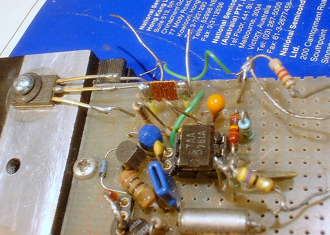
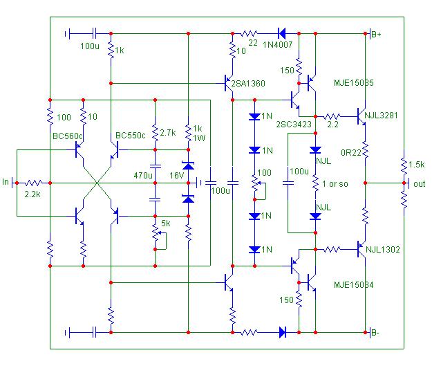
http://www.diyaudio.com/forums/atta...etrical-amplifier-ssa-mihai-output-buffer.jpg
Playing around with the TT diode bias spreader (no series resistor), I found that at about 30mA current I get about 18mV over the 0R2 emitter resistor. At 50mA through the diodes, I get about 30mV over the resistor, and at 100mA the output bias increases to about 55mV. Bias current would be 90mA, 150mA, and 265mA, respectively. Nothing earth shaking there, but here's the question:
I've read that optimal AB bias is around 18mV at the emitter. But in order to get that for this schematic, I'd have to reduce the current through the CFP driver to around 30mA. So what are the trade offs here? Or, can I just push more current through the outputs with impunity (assuming adequate cooling)? And, what should be the minimum for the CFP driver?
Sheldon

My take:
Thought occurs that the zeners are now unnecessary. Maybe the diodes across the bridge too?
Sheldon
- Status
- Not open for further replies.
- Home
- Amplifiers
- Solid State
- TGM5 - all-BJT Simple Symmetric Amplifier