... systems comprising line arrays and point source subs can be adjusted to have the desired sub/array spl balance only at one particular distance, due to the differing attenuation rates of both.
In my room with my setup I'm not quite getting this behavior. I have point source subs located at the line array and due to the room I still get peaks and dips throughout. I'd like to do distribute bass but don't have the space. Due to this problem when I move closer to the arrays I get less bass not more.
When into the Schroeder I'm not sure everything behaves ideally. With the swarm the subs are located physically close and far away from the listening position, does the "point source" nature of the averaged multiple sources which smooth out standing waves still behave like a point source moving from the line array distance?
I have difficulty with this concept so is there more information on this subject that I can read about? Thanks for your time.
Any chance you have a rather symmetrical setup? That could mean you get the dips on both sides at similar frequency ranges. My arrangement is asymmetrical, as in one side has a side wall while the other side opens up to a much bigger space. This makes their respective dips land in differing frequency ranges.
This allows me to swap energy from my arrays. left to right and vice versa, to soften the holes of the other one. I've shown many graphs that show that. Adding subs will make it easier for me I suppose, but lets wait and see what happens there.
To find more theory on the use of multiple subs a good start would be to look for the theory from Dr. Earl Geddes. With any luck this paper will be available/accessible from his website. (did the search for you, here it is):
http://www.gedlee.com/Papers/multiple%20subs.pdf
Even without that paper there's enough to find on this forum to get the general idea. I even remember an App that Dr. Geddes wrote where you can simulate the room with several different subs and subwoofer positions. It would be ideal to be able to EQ each separate subwoofer to make up for any holes of the others in the swarm. Make use of it's strengths and back off where it has a deep null. I don't think the app is still around as some where having troubles with the requirements for the software. I got to play with it, it was interesting!
Also try threads like this: Multiple Small Subs - Geddes Approach and Geddes Bandpass Subs and the Multi-sub approach.
There's also a JBL paper floating around on the net about the use of multiple subwoofers. That's another good read!
here's the presentation about it: https://www.harman.com/sites/default/files/multsubs_0.pdf
Do you run the arrays fullrange? With boost on the bottom end? If so, a different position for one of the subs could do wonders already. Geddes advocates different places for each sub and trying different heights as this helps to even out the bottom end response (*). If I remember correctly his advice is to use at least 3 of them. They don't have to be identical, in fact, it could be beneficial if they are not.
(*) as Juhazi pointed out to you in the previous post
Last edited:
Here is a link to multi-sub optimizer software. I haven't run it yet but saved if for future use
https://www.andyc.diy-audio-engineering.org/mso/html/
https://www.andyc.diy-audio-engineering.org/mso/html/
Ronald, I’ve found what I think is your final wiring scheme:
https://www.diyaudio.com/forums/ful...-driver-range-line-array-183.html#post5095849
If you have the time (and the memory), can you recap what you actually settled on? I know you did some wire testing and I believe you used different gauges depending on the length of wire run and type of connection. IIRC, you also had some back-and-forth about the benefits of series-parallel versus parallel-series. From a purely selfish standpoint I wish you had some photos of the wiring but, as I recall, you already had the stuffing in before you thought to take any wiring photos.
For those who are considering a project of this scale it would be of great historical benefit to have this information. Thanks again for your contributions to the forum.
Ronald, I’ve found what I think is your final wiring scheme:
https://www.diyaudio.com/forums/ful...-driver-range-line-array-183.html#post5095849
If you have the time (and the memory), can you recap what you actually settled on? I know you did some wire testing and I believe you used different gauges depending on the length of wire run and type of connection. IIRC, you also had some back-and-forth about the benefits of series-parallel versus parallel-series. From a purely selfish standpoint I wish you had some photos of the wiring but, as I recall, you already had the stuffing in before you thought to take any wiring photos.
For those who are considering a project of this scale it would be of great historical benefit to have this information. Thanks again for your contributions to the forum.
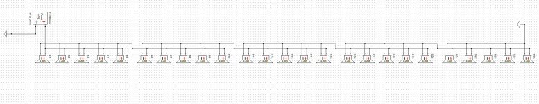
The wiring scheme I have used is series/parallel. The thin wire I bought for that was a highly flexible 1.5 mm2 OFC type wire with PVC coating. Basically specked as a quality speaker wire. It consisted of multiple thin strands of copper that made it flexible.
The longer runs were of the same type, just a bit thicker.
In hindsight I would not use that type of wire again. Nor the connection scheme. Parallel/series wiring has some advantages, mainly around the impedance peak of the drivers. I'd also use wire wit a lesser number of strands, which would make it more stiff, harder to handle, but does have advantages at higher frequencies.
I did some testing that should be documented somewhere in this thread on using long runs of speaker wire. Among those I used solid copper electrical wire as used inside my home for the power outlets and a limited strand count wire of the same (I believe 2.5 mm2) thickness. It showed an improvement at high frequencies compared to the flexible multistrand type wire, even after FIR filters were applied.
The schematic I'd use today is:
The wires I'd use in future projects would be something like ~ 7 strand 1.5 mm2 wire for the shorter runs and 2.5 mm2 for the longer runs with the same type of strands, just more of them.
The only reason not to go for complete solid wire is the hassle with the stiffness, making it hard to run it inside an enclosure and making sure it stays put when closing the array.
I could not take any pictures during the wire job as the wiring is indeed below the damping material and is being run trough holes in the braces. I put it in there part by part, soldering it as I went along.
I did take pictures, they just did not show anything particularly useful
") .
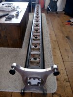
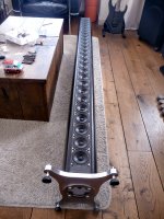
.Here are some I probably did not show before:
Closing up the array:
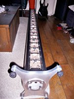
Here's another I found, showing the pre-cut short wires at the right side of the picture (this must have been the first array being wired up):
Taken at the end of a dark December day of wiring
I still want to re-wire some day. I just lack the time and space to do so. I'd need the house to myself for about 2 days per speaker, with more time to prep in advance and that rarely happens.
Attachments
Last edited:
Thank you, Ronald. This is extremely helpful and it further shows your willingness to not rest on your laurels for what is already a spectacular build, but rather to continue to pursue excellence and improvement in your design. Many people will continue to benefit from your generous sharing of information.
About ordinary cables i'm not too good myself about over time have more or less build up some preferences based mostly on a subjective experience : ) anybody interested reading some objective data for cables look links below.
Analog audio cables:
https://www.audiosciencereview.com/...s/ethan-winer-builds-a-wire-null-tester.5197/
USB audio cables:
https://www.audiosciencereview.com/...s/do-usb-audio-cables-make-a-difference.1887/
Analog audio cables:
https://www.audiosciencereview.com/...s/ethan-winer-builds-a-wire-null-tester.5197/
USB audio cables:
https://www.audiosciencereview.com/...s/do-usb-audio-cables-make-a-difference.1887/
That’s a great build there. Let me know if you want some free tweeters if you need a little in the high end. They are those ones from Part Express when they had that 200 tweeters for a real cheap close out deal
Just pay for the shipping I think maybe 6 or 8 of each side would bring them up above the 4000k to 18,000k. They are yours if you want them


Just pay for the shipping I think maybe 6 or 8 of each side would bring them up above the 4000k to 18,000k. They are yours if you want them
Thank you, Ronald. This is extremely helpful and it further shows your willingness to not rest on your laurels for what is already a spectacular build, but rather to continue to pursue excellence and improvement in your design. Many people will continue to benefit from your generous sharing of information.
You're welcome CraigSu,
I'm hoping my sharing is contagious, I believe we can all learn something from one-another and together achieve great things.
About ordinary cables i'm not too good myself about over time have more or less build up some preferences based mostly on a subjective experience : ) anybody interested reading some objective data for cables look links below.
Analog audio cables:
https://www.audiosciencereview.com/...s/ethan-winer-builds-a-wire-null-tester.5197/
USB audio cables:
https://www.audiosciencereview.com/...s/do-usb-audio-cables-make-a-difference.1887/
I was hesitant to say anything about cables/wires. Personally I don't believe in overpriced wiring, but I do believe quality differences do exist. I would like to get what I pay for, nothing more, nothing less.
I took a look at that first thread and noticed this wire test:
https://www.audiosciencereview.com/forum/index.php?threads/when-12-gauge-wire-is-not-12-gauge.3/
If anything, my wiring resembled the Monoprice, where stripping the wire would loose you a couple of strands at least. With the longer runs of wire within an array it would be nice to get the actual gauge one pays for
.That’s a great build there. Let me know if you want some free tweeters if you need a little in the high end. They are those ones from Part Express when they had that 200 tweeters for a real cheap close out deal
Just pay for the shipping I think maybe 6 or 8 of each side would bring them up above the 4000k to 18,000k. They are yours if you want them
View attachment 715422 View attachment 715423
Thanks for the compliment and the generous offer! I'd take you up on that if I thought I would need more on the high end. However I don't feel/think I'm missing out there so my focus right now is on other things
.I do appreciate such an offer though! Good to see people like you are around!
The "other things" I'm focussed on are things like the cross talk between our ears (left ear hearing right speaker and vice versa), I still believe there's something to be gained there. My experiments in that field were fun and showed a lot of potential. The mid/side EQ I run is still part of that. I think it's one of the biggest "problems" or "flaws" within Stereo reproduction.
Hi Wesayso,
While working on room correction for my new open baffle speakers I came up with a for me unparalleled realistic sound. So I thought I did the room correction right, but it turned out that I made a mistake with the setting of the filters. It turned out that the response that I was listening to has dips around 600 and 3000 Hz. After searching for the BBC dip on the internet I came across your mid-side filter approach (with dips at 6000 3700 and 7200 Hz!), and I tried this on my system, using Media Player Classic with the convolver plugin. This sounds really good!
I am wondering: how did you come to this specific filter design? Was it tweaked purely on listening perception or were you using a different bases (HRTF measurement data or so). And did you find any further improvements on this?
Hi hulsebos,
A combination of both, actually. I started with simple EQ based on preference in listening. But it soon showed differences in preference between the phantom parts (mainly noticed in vocals) and side panned parts. This resulted in some simple mid/side tweaks that seemed to help. At that time, primarily something much like the BBC dip and an enhancement build into JRiver's media player called "surround field".
So I started to investigate what was causing this deviation in preference. Around the same time this thread came up and I decided to try a bit harder to get to the bottom of it.
I've made sims in REW based on actual listening distances and tried more than one "cure". I participated in the above thread but also tried to find answers for my own particular setup with experiments and sims. (lots of fun!)
Currently I have that mid/side EQ implemented, as documented in this thread, combined with my ambient back channels which also play a role to correct part of this cross talk we experience. Within the Haas limit we can influence the sound we perceive and thereby "trick" our minds even stronger.
The mid/side EQ removes excess energy as perceived in the phantom center, while it recreates the correct balance for side panned sounds. The ambient channels fill in some of the dips, created by the cross talk, we experience in phantom sounds. Together it gives me a more vivid soundscape, closer in perception to a real performance.
The other things I have tried, cross talk cancelation and the phase tricks as outlined in the linked thread both work too, to an extend. But they were more position dependent than this more subtle mid/side EQ I created.
However the other experiments did show me there's more to be had, and I will continue to pursue means to get me closer to the positives from each of these methods, while trying to keep the benefits I have right now. With that I mean that I don't want to give up good sound all along my couch for great sound in the exact sweet spot.
Future plans include a center helper (not a real center channel) to see what that could bring me. It's main job would be to fill in the dips created by our two ears in relation to speaker position. Though the plans keep bubling in my mind, I still need to determine what I would need for this experiment. I'm trying to find suitable ways to do what I want and at the same time keep my girl happy (she won't like the idea of even more speakers scattered around the living room).
The mid/side trickery and ambient help is 'a work in progress' too. Fun to read you found this thread by googling. I use my setup as a continuous "lab" to play with and learn from and document it in this thread.
Last edited:
I'm taking things a bit slower with progress on the subs, sorry for that. I've decided to hunt a solution to implement the amplifier in the back of the subs, and this will take me some time to do it to my liking.
Most probably I will choose an aluminium enclosure for the amp to sit in, which will be flush on the back side with the sub, with a heatsink covering that hole, except a small part on the bottom where it will be closed off by a block that integrates all the needed connections. I may print that part on a commercial printer or I'll have to get creative with my wood work.
Do it right the first time is my motto, so I'm taking this slow. I didn't quite succeed to do it right in one go with the arrays (lol). But it has taught me a thing or two about patience.
The outside temperatures dropped over here, so I can't start with the epoxy/paint anyway.
In the mean time I still have music to listen to at a satisfying level, so no harm there.
If you want the easy way, (nothing I have seen here was the easy way) parts express has some DSP plate amps with matching but separate steel housings.
Dayton Audio SPA-F Subwoofer Plate Amplifier Mounting Frame for SPA250DSP and SPA500DSP
Dayton Audio SPA-F Subwoofer Plate Amplifier Mounting Frame for SPA250DSP and SPA500DSP
Last edited:
Yes, it seems I never go for the simple solutions
I had looked at the plate amps from Dayton as well as the plate amps from Hypex. They both feature onboard DSP modules I don't really need (plus an extra conversion from A-D-A).
I already have some Hypex amps, I just need to take care of their enclosure.
Hypex Electronics B.V.
It won't be that hard, I just needed to figure out a space saving option as they cannot stick out too much at the back side. I've thought it true and am considering a few different aluminium enclosures at the moment, as well as a mute switch. I have the cable set and input plus power socket with fuse and switch. I want it nice and tidy, as if it were a factory look.
The most practical solution for me is to have the power cable coming out on the bottom below the heat sink. I can draw up anything I want and have it printed at a firm like Shapeways. I have access to lots of filament printers at work but don't regard that as a valid option.
My original plan was a separate enclosure for the amp, but it would always get in the way somehow and I'd loose some freedom of placement of the subs. It really isn't a big problem to solve but I want to do it right in one go. Which means I have to think things trough a bit. I am in no hurry to get it finished. I won't paint the subs if outside temperatures (and in the garage) are too low. So this gives me some time. All the mayor construction is done, the amp will be easy after that.
 )
)- Home
- Loudspeakers
- Full Range
- The making of: The Two Towers (a 25 driver Full Range line array)