
Hello sir,
First of all, compliments for the enormous and well-documented thread you have on hands. I have just started reading and I think I will have a lot of try-outs and experiments in the reading I still have ahead of me. A lot of info is on point.
I wish I was knowledgeable enough to help you out here, but I'm limited in experience with one tweeter only. I do plan on having an experimental array of vintage ribbon tweeters, but I am struggling to source enough of them to make an array that covers the range that my ears travel when sitting and standing. I will be delighted to hear about your solutions regarding this and wish you the best of luck with your project.
Sincerely,
Thanks for the kind words!
Maybe an enlarged version of the foam pads one of those RAAL tweeters has would suffice?
I've tried it with pillow stuffing on a pair of large MTM's and they sounded more open and detailed, where before they sounded quite suffocated in the higher mids and highs.
Measurement data looked almost exactly like it would have been one larger driver, but with better vertical dispersion IIRC.
Definitely has been on my mind, however I could not imagine making it look good
") . So I did not even experiment with it. I've also played with a thought of trying to place something before the cones as an equalizer for path lengths. But that suffered the same faith.
. So I did not even experiment with it. I've also played with a thought of trying to place something before the cones as an equalizer for path lengths. But that suffered the same faith. Time will tell if these passive shading algorithms will help get an even higher level of performance. If not, I'm out some money for components but will have learned something as well.
I've treated these arrays as an ongoing experimental setup, trying all sorts of things, not all equally successful but most certainly educational and even fun in the process.
As long as I can come up with ideas and/or experiments I will continue... at least as long as I'm enjoying the process and continue to learn from it. It isn't a burden to listen to good music, is it? I've enjoyed my ride immensely and have had a good time interacting about it here.
My line array version with 9 Aurum Cantus G3 ribbons and 12 CSS 4.5 inch woofers from some 15 years ago. Active DSP crossover with DEQX processor.
You've had many different setups
, any favorites?For me, this has become a personal quest of trying to eak out as much as I can out of this compromise I've made. The full range array. So far it hasn't been a disappointment. I've enjoyed this ride more than I had hoped for. And i'm not done yet!
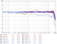
I tried to combine all favourable parts of the sims I did so far.
Not easy to find the right mix, I'll tell you that. Here's an impression of some of the changes I went trough:

If you look at the red line in the Power & DI graph, you'll see what I've been after. The third graph I show here already came close, but still left me wanting more (Shaded 9.0). Then a short detour followed (up until shaded 12.0a), that favoured another direction, only to end up very close to where I was before (but just that hair better)...
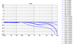
I think even the Filter graph tells the story, you see less wiggles in the last iteration, meaning the results are more even across the board even before the DSP step.
I can't promise this will be it... I might go into another detour again.
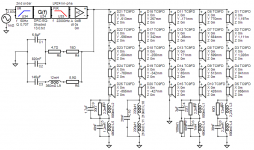
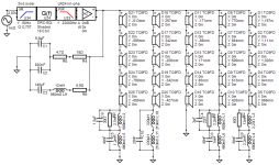
But the graphs should tell some of this story anyway. Slowly but surely I've locked into the smoothest graph so far. Again, a little different than the last one I presented, an updated schematic:

At some point I'll have to just bite the bullet and call it done... I can't believe how many sims I ran already.
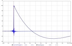
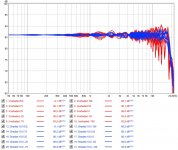
The IR and STEP:

Not easy to find the right mix, I'll tell you that. Here's an impression of some of the changes I went trough:
If you look at the red line in the Power & DI graph, you'll see what I've been after. The third graph I show here already came close, but still left me wanting more (Shaded 9.0). Then a short detour followed (up until shaded 12.0a), that favoured another direction, only to end up very close to where I was before (but just that hair better)...
I think even the Filter graph tells the story, you see less wiggles in the last iteration, meaning the results are more even across the board even before the DSP step.
I can't promise this will be it... I might go into another detour again
.But the graphs should tell some of this story anyway. Slowly but surely I've locked into the smoothest graph so far. Again, a little different than the last one I presented, an updated schematic:
At some point I'll have to just bite the bullet and call it done... I can't believe how many sims I ran already.
The IR and STEP:
Attachments
Last edited:
I guess I'm at a turning point. I was trying hard to keep improving the Directivity Index, but as a result the standing height gets a darker sound too.
So time to make compromises again? I tried to cheat by creating a more asymmetrical pattern (Below a certain point I don't need an even response) but it turned out to be a little harder than I thought.
Here's the comparison:

See that there's a clear difference in the top end? A reduction in side bands which are responsible for the sharp cornered DI change? However it also results in a balance difference at standing height. The improved directivity curve results in a darker top end if one moves up or down...
Maybe one more attempt trying to get in the middle of these two? (lol) Does it ever end....
I'm trying to keep a close eye on the heights that are most probable in day to day listening scenarios. (plus keeping in mind that I'm the tallest one in our family here, to everything at 1 M, just above it and most below it would be important to me. Say from 1.025 to 0.925 listening height.

So time to make compromises again? I tried to cheat by creating a more asymmetrical pattern (Below a certain point I don't need an even response) but it turned out to be a little harder than I thought.
Here's the comparison:
See that there's a clear difference in the top end? A reduction in side bands which are responsible for the sharp cornered DI change? However it also results in a balance difference at standing height. The improved directivity curve results in a darker top end if one moves up or down...
Maybe one more attempt trying to get in the middle of these two? (lol) Does it ever end....
I'm trying to keep a close eye on the heights that are most probable in day to day listening scenarios. (plus keeping in mind that I'm the tallest one in our family here, to everything at 1 M, just above it and most below it would be important to me. Say from 1.025 to 0.925 listening height.
Attachments
This is almost a daily update (lol)...
I've tried to optimise the DI, as said. However it has not been as successful as planned. I need some interference to keep my goal of good/reasonable standing performance. Robbing the bottom energy (because I don't need it) to improve the DI leads to a more unbalanced result at the desired (design) heights.
So I'm back to where I was a couple of days ago and I'll try to optimise the parts count while keeping the performance.
It remains a compromise to choose from. Better DI is possible but leads to a sitting height only performance upgrade. So in order to keep my goals I need to compromise here. It still is a world of difference between shaded and unshaded with the theoretical advantage leaning towards (frequency dependent) shading.
There is no way of knowing what it will do until we try. While it is better on paper might not mean it also sounds better in real world applications.
Comparison over a 10 height difference (where most of the time our heads will be )

Over this limited height the shaded array is at least as good if not better behaved (even if psy smoothing is applied).
The raw responses over a 20 cm height difference:

Here it is no contest, the shaded array wins everywhere. Up till about 8 Khz the unshaded array is doing a pretty good job, just not as good as the shaded array.
)Over this limited height the shaded array is at least as good if not better behaved (even if psy smoothing is applied).
The raw responses over a 20 cm height difference:
Here it is no contest, the shaded array wins everywhere. Up till about 8 Khz the unshaded array is doing a pretty good job, just not as good as the shaded array.
Attachments
Last edited:
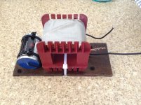
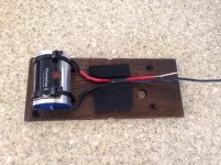
Trying to get a feel for size...

All components of one of the 4 circuits mounted on a 80 x 120 mm prototype board.
Audyn Q4 cap, Jantzen coils, Jantzen superes mox resistors and a couple of vishay caps. It does require quite a bit of room due to using coils that have reasonable resistance numbers (1mm wire).
Total volume is about 0.088 litre. That's ideal of having 3D designs...
(yes, I should move those Vishay caps)
Attachments

Last edited:
I'm kind of trying to figure out what material to use for the crossover board.
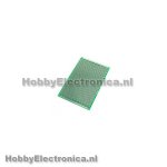
I can find these in 80x120mm:

But no material is stated, I've asked by mail at the shop. It could be FR4, but could also be a phenolic type board. I wanted single sided copper sleeves for the holes but could not find it that easy locally. Mostly offerings from China and I won't try that right now.
I've also looked at this:

(size: 80x500mm, 2mm thickness)
Basically blank FR4 board with enough material to cut 4 boards per piece. But drilling and cutting to size can be awkward with FR4. The material is hard and ideally you'd need a diamond type (rotary) saw blade and/or carbide drill bits.
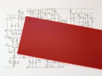
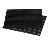
I also found these:

(size: 88,9 x 127,0 mm)
A few different colors phenolic boards, no copper and specifically meant for crossovers.
Slightly bigger than my desired 80x120mm but not by much. (opening of enclosure is 80mm but I could wiggle it in I suppose)
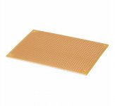
The same firm also carries these:

(size: 79,4 x 109,5 mm)
Also phenolic and slightly smaller than my goal (about 1 cm short) but it could still be made to work. Single sided copper at the holes and the phenolic should be easier to drill using HSS drill bits for things like cable ties.
I liked the crossover examples from Tony: Humble Homemade Hifi - Crossover Assembly
He does use pré-drilled FR4 boards, and apparently sometimes cuts them to size. Despite the difference in material, it looks a lot like the black boards I showed above.
Any advice on what to pick? Phenolic should be good enough, right?
I can find these in 80x120mm:
But no material is stated, I've asked by mail at the shop. It could be FR4, but could also be a phenolic type board. I wanted single sided copper sleeves for the holes but could not find it that easy locally. Mostly offerings from China and I won't try that right now.
I've also looked at this:
(size: 80x500mm, 2mm thickness)
Basically blank FR4 board with enough material to cut 4 boards per piece. But drilling and cutting to size can be awkward with FR4. The material is hard and ideally you'd need a diamond type (rotary) saw blade and/or carbide drill bits.
I also found these:
(size: 88,9 x 127,0 mm)
A few different colors phenolic boards, no copper and specifically meant for crossovers.
Slightly bigger than my desired 80x120mm but not by much. (opening of enclosure is 80mm but I could wiggle it in I suppose)
The same firm also carries these:
(size: 79,4 x 109,5 mm)
Also phenolic and slightly smaller than my goal (about 1 cm short) but it could still be made to work. Single sided copper at the holes and the phenolic should be easier to drill using HSS drill bits for things like cable ties.
I liked the crossover examples from Tony: Humble Homemade Hifi - Crossover Assembly
He does use pré-drilled FR4 boards, and apparently sometimes cuts them to size. Despite the difference in material, it looks a lot like the black boards I showed above.
Any advice on what to pick? Phenolic should be good enough, right?
Attachments
Last edited:
Mostly offerings from China and I won't try that right now.
You can probably bet that the "local" stuff was probably made in China anyway....
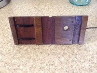
I prefer something solid that you drill holes in for cable ties or glue to.
Troels way of doing it, epoxying the parts to a piece of thin ply seems like a sensible way to me too. Easy to attach the timber to the carcass and can be any size you like
Point to point wiring is usually quite easy with these sort of components and a solder tag or similar works if you need a common point.
I tried to combine all favourable parts of the sims I did so far.
Not easy to find the right mix, I'll tell you that. Here's an impression of some of the changes I went trough:
If you look at the red line in the Power & DI graph, you'll see what I've been after.
Which line is the power response? My power response and on-axis response are mostly identical. This makes sense because for the most part, the unshaded array has nearly the same directivity over the entire range. Even with shading, the goal is to keep the same directivity. Are we doomed in that we may never achieve increasing directivity?
The darker blue line in the Power and DI graph is the predicted power response.
It might be the listening window in green that is very similar to the on axis response, if it is the darker blue line then something has gone wrong because the array has an increasing directivity index therefore the power response must fall.
In general the power response and DI are mirror images of each other.
You can probably bet that the "local" stuff was probably made in China anyway....
True, but the travel route from China has never been speedy but due to the virus situation there have been lots of non arrivals.
- Home
- Loudspeakers
- Full Range
- The making of: The Two Towers (a 25 driver Full Range line array)