I like it! What did you use for an umbilical cord? Do you really hear an audible difference in noise, etc. as compared to a more traditional arrangement? Regardless, it certainly appears you're enjoying the fruits of your labor.
I'd always shied away from umbilicals because of concerns about insulation/arcing in the connectors. Those were quickly dispelled when I inherited an old Amp Supply linear RF amp, which spewed a lusty 3500V (count 'em!) through an umbilical into a pair of hungry 3-500Zs. 😱 Holy behemoth, Batman - that really put the 300-500 VDC we normally use into perspective!
So yeah, I'm super-stoked to get started on the RLD. I was going to begin in 2011 (see post 797) but life sort of got in the way. You know, little stuff like grad school, a new career, and a move halfway across the country from NC to KC. 😛 The cool thing is 1) I can begin my build with the "correct" 8k output iron, 2) my stock o' tools and skills has grown, and 3) I'm 5 years wiser. I think.
I think the vibrations from the power transformer does affect the rest of the amp. At least in my experience. I found my cables on eBay that had octal plugs on the end. Amphenal plugs are better.
Look at post 17
http://www.diyaudio.com/forums/tubes-valves/262250-1kv-umbilical-cords-other-hv-issues-2.html
Look at post 17
http://www.diyaudio.com/forums/tubes-valves/262250-1kv-umbilical-cords-other-hv-issues-2.html
Hi
I have played music for a year. Every weekend for atleast one year. My amp is a RLD. And it works perfrect. I use tubes that I bought from 'JJ electronics'
I just want to say that this amp works. And it sounds great.
Cheers!
Rolf
I have played music for a year. Every weekend for atleast one year. My amp is a RLD. And it works perfrect. I use tubes that I bought from 'JJ electronics'
I just want to say that this amp works. And it sounds great.
Cheers!
Rolf
It's -3dB. Remember phase.
I have had the itch to make an EL84 amplifier and in reading through this build thread I remembered my silly question not too long ago that SY was kind enough to answer for me. As most of you know that voltage is leading by 90 degrees for an inductor and lagging 90 for a cap I just want to show it via a graph. My question was that if you calculated the reactance of a cap or an inductor and use the equivalent value resistor to create a "voltage divider" you would think the outcome would be -6db, but as SY brilliantly pointed out to me that phase plays a role in the answer. Here I simulated a 1H inductor which it's reactance @ 1kHz is 6,280, then I used the same value resistor for the filter. For me it helps to see where the peak waveforms are in relation to time, it shows that because of phase it is indeed -3db and not -6db. Most of you out there are very smart and probably find this rudimentary but there are some like me that this will help to see what is actually going on. Oh and I did work through the math but it gave me a headache and figured I wouldn't bore anyone with that. 😱
Thanks again SY for all you infinite wisdom!!
Attachments

Go to https://oshpark.com/shared_projects/rkU0U4LT pay them $17 and in about 3 weeks you'll get 3 of these at your door. This is untested, but it is hard to imagine what could go wrong.
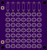
Wouldn't this be more cool if you line these LEDs up into undergrow on the amp?
I've been collecting parts to build this amp for quite a while and am now ready to finally plunge in. I have two amps with donor potential.
Amp one is an Eico ST-40 which, using 7591's has 6.6k output transformers, so not ideal. The other is a Dynaco ST-70 using EL-34s with 3.5k transformers. I could use this one with a different tap or, correct me if I'm wrong, parallel two EL-84s and use it as is.
I could also redesign the amp to use more appropriate tubes, but I don't feel I have the skills to confidently do that. Or I could buy new iron.
I'd like to hear others opinions on the most sensible way to proceed.
Thanks!
Sent from my iPhone using Tapatalk
Hi staggerlee,
Eico products are very good, please don't do anything but restore your Eico. I have an ST-70 I will be restoring and would never think of using it as a part source or "donor" amplifier. The ST-70 also uses 7591A output tubes. You would be further ahead to buy new iron for your project. Either that, or restore the ST-40 (but do it properly!).
-Chris
Better iron can be had. Hammond is designing new output transformers for a build of an HF-87, new right from scratch. I get to hear the new one vs the original HF-87 I rebuilt a few years ago.
-Chris
-Chris
VF=6.25V -- http://www.osram-os.com/Graphics/XPic8/00243180_0.pdf
will need some fancy heat-sinking putting 2 in series.
will need some fancy heat-sinking putting 2 in series.
Use the 6.6k iron. Yes, the Eico is nice, but it's your project, do what you like!
Folks who designed the Eico (when the company was in Flushing NY) also seem to have worked for Pilot and Lafayette.
Hi staggerlee,
Eico products are very good, please don't do anything but restore your Eico. I have an ST-70 I will be restoring and would never think of using it as a part source or "donor" amplifier. The ST-70 also uses 7591A output tubes. You would be further ahead to buy new iron for your project. Either that, or restore the ST-40 (but do it properly!).
-Chris
Chris, the 70 is a Dynaco the 40 is an Eico, point taken though. Restoring those would be enjoyable. Once I've finished the RLD. And my pre amp. And my phono stage. And new speakers!
Chris, the 70 is a Dynaco the 40 is an Eico....
Point of clarification: Eico made both an ST70 and an ST40. Both with 7591s. The difference being that the 70 was fixed bias and 35 watts a side and the 40 was auto bias at 20 watts per.
Hi staggerlee,
No. Eico made an ST-70 as well. It uses 7591A tubes and I have one sitting right here. It looks very much like the ST-40 and is only a little more powerful.
I'm just about to restore a McIntosh MA-230 that uses the 7591A tubes for outputs. I hope the owner will be pleased with the rebuild. It's been a long while since I have heard a pair of 7591A tubes singing. Looking forward to his running properly again.
-Chris
No. Eico made an ST-70 as well. It uses 7591A tubes and I have one sitting right here. It looks very much like the ST-40 and is only a little more powerful.
I think so. I'm looking forward to mine. I was waiting for tubes for years, now that I have them, I ran out of time. Life can be like that. I hope yours ends up to be everything you hoped for. They are pretty in their own way.Restoring those would be enjoyable.
I'm just about to restore a McIntosh MA-230 that uses the 7591A tubes for outputs. I hope the owner will be pleased with the rebuild. It's been a long while since I have heard a pair of 7591A tubes singing. Looking forward to his running properly again.
-Chris
Point of clarification: Eico made both an ST70 and an ST40. Both with 7591s. The difference being that the 70 was fixed bias and 35 watts a side and the 40 was auto bias at 20 watts per.
Right, half the time when I Google Dynaco ST70 the top hits are the wrong one!
What do you mean by "properly restore"? When I say restore I mean electrically restore bi. I'd definitely replace the electrolytics and paper caps. In the case of the Dynaco, I'd probably (tastefully) upgrade the power supply as well.You would be further ahead to buy new iron for your project. Either that, or restore the ST-40 (but do it properly!).
Ever watch Mr. Carlson's videos on YouTube? He restores and modifies vintage radio and test gear. Its a great way to spend a Sunday!
Ok two posts and I'm already off topic.
Last edited:
Hi staggerlee,
Yes, a thoughtful and careful restoration targeting the circuitry. There's nothing nicer than listening to something you have just restored knowing that you've extended its life another 40 ~ 50 years or more.
I haven't heard of Mr. Carlson's videos on YouTube. Of course, my computer has no sound, so that would be pointless for me. Sounds like an interesting time.
-Chris
Hi all!
Due to 6L6's activity in this thread, searching for a build using that tube type is a somewhat challenging exercise. 🙂
Had anyone made a version with 6L6's in it, an what changes needed to be made to accommodate?
Thanks!
Due to 6L6's activity in this thread, searching for a build using that tube type is a somewhat challenging exercise. 🙂
Had anyone made a version with 6L6's in it, an what changes needed to be made to accommodate?
Thanks!
The RLD runs in pentode, so you'll actually need to use a pentode tube, like the EL34, instead of the beam power tetrode 6L6. EDIT: I'm confusing suppressor grid and screen, yes, 6L6 and other beam power tetrodes can be used.
Certain things will need to be made bigger - higher current transformers, bigger output transformers with appropriate windings for EL34, the LED string will be longer to make bias voltage a bit higher, etc...
Overall the changes will be needed to accommodate the differences in the output tubes. Much of the rest of the circuit will be the same.
I looked into it a while ago, thought it would be an interesting and straightforward change. (And then never followed through only because I already have power and output transformers for the (EL84) project)
Last edited:
- Home
- Amplifiers
- Tubes / Valves
- The Red Light District - another PP EL84 amp