The right angle SMA works well to avoid stress. I installed one and from that perspective it works well. Again if you are going with ReclockPi, that can be tricky. I use only one clock so I pointed it toward the front of FIFO so there is room for the connector. The cable just clears the pcb mount, then secure the cable mechanically to isolate the FIFO stack from stress if there is a tug on the cable. Another way that works very well which I am using until final cables arrive is a U.FL terminated RF patch cable. They have a right angle U.FL on the end that attaches to the squarer pcb and whatever SMA you want on the other. These are used commercially to provide the SMA outlet on the chassis and connect to the PCB. Works great and there is no stress and fits neatly under ReclockPi. I simply soldered both a U.FL connector and the right angle SMA onto the squarer to provide both connection alternatives.
I use the right angled sma connectors and I also wondered if there can be an issue with the angle style.
But as sma is specified for much higher frequencies as we are using it should be ok?
Anyway, I ordered an extra set squarer boards and straight sma connectors for my future reclockpi.
as we have proven to be going extra mile on everything... maybe that can be something to keep under consideration in the whole picture.
surely each element contributes little to nothing... summed together can lead to some improvements.
Surely if someone is taking the trouble to cast lead over a crystal in the purse of the "ultimate-vibration-free" setup, maybe is also worth to keep in mind that an RF signal is not something that can be managed with approximations. Surely RF can't be reduced to a matter of ergonomics. Better-to-wire/handle almost never translate to also something good for the signal.
That is more true more the freq is high. The effects can be minor at the frequencies we play with, but surely, some degradation can be discovered if properly analyzed.
if that can be heard.... is a whole other matter.
Hello,
If you tell someone that you just spend this much money on '' clock circuitry '' . On top of that you will have to invest some money on a proper supply to make it work.
Of course to make things as they should we must go for cables and connectors which are designed for this kind of circuitry. If it requires a connector on both sides it wont wont work if you just make a direct soldering i think because you mess up the technical specs or not?
IF i can have a tiny improvement by making two molds, heating up some lead, drilling a grommet hole. It wont be time consuming.
We will see.
Greetings, Eduard
P.s Of course the easy way out will be saying that it wont matter that much BUT then i think you should have bought the Accusilon and be happy!
If it requires a connector on both sides it wont wont work if you just make a direct soldering i think because you mess up the technical specs or not?
A direct soldered connection is not always the best option.
Especially for RF.
Technical specs are perfectly fine. Andrea did a very fine job in trying to keep the impedance matched all over the pcb. Weak points are where the signal enters/exits the board. Good connection practices are mandatory IF you care about signal integrity.
For example, No lab equipment (to my knowledge...) that works with RF has ever used soldered coaxial cable to carry signals across intel sections.
Just take a peek of some serious spectrum analyzer and you will see rigid coax all'overs (not always, but for very high frequency stuff is a must).
If something works for 10Ghz, surely works for the 45Mhz (or so...).
If something works fine for DC, surely won't work as well for 45Mhz.
IF i can have a tiny improvement by making two molds, heating up some lead, drilling a grommet hole. It wont be time consuming.
You can do whatever you feel right.
Please just don't use "time" as a measure of effectiveness or to legimitate an attempt
")
Surely, more you know, less you will "waste" during your journey toward clocked-happiness.
P.s Of course the easy way out will be saying that it wont matter that much BUT then i think you should have bought the Accusilon and be happy!
If someone will take one of SOTA's oscillators from Andrea, AS-IS, using the bare minimum accessory components required to make them run... you will still get an improvement over ANY accusilicon
The extra hassle we (me fore sure...) are taking is product of a some masochistic approach: a blend of "because i can" and "because i want", all of that plus a sprinkles of theory around
Last edited:
So a question or two.
Has anyone especially in the U. S. Ordered cables from superbat as suggested and if so how long was delivery. I have been waiting three weeks so far.
Second question. I notice that the sma on the board grounds to the case through the toothed washer. The power however is not grounding to the case. The anodizing seems to be acting as an insulator. I assume that I should scratch away at the anodizing around the power connection to ensure a solid ground between the power and the case as well?
Hello,
I think this kind of information should be in the manual.
If you see a manual for an amp kit for instance it is always told if the cinch connectors are grounded, the location where the circuit is connected to the chassis, it is anodized it is always told to make sure there is a proper contact.
Even if things in this situation dont matter it should be told because people will think it does.
Greetings, eduard
So a question or two.
Has anyone especially in the U. S. Ordered cables from superbat as suggested and if so how long was delivery. I have been waiting three weeks so far.
Second question. I notice that the sma on the board grounds to the case through the toothed washer. The power however is not grounding to the case. The anodizing seems to be acting as an insulator. I assume that I should scratch away at the anodizing around the power connection to ensure a solid ground between the power and the case as well?
We have made the measurement with the oscillator in the standard Hammond box merely removing the plastic flanges.
BTW, you can scratch the anodizing of the case parts to get better electrical continuity between them.
So a question or two.
Has anyone especially in the U. S. Ordered cables from superbat as suggested and if so how long was delivery. I have been waiting three weeks so far.
Second question. I notice that the sma on the board grounds to the case through the toothed washer. The power however is not grounding to the case. The anodizing seems to be acting as an insulator. I assume that I should scratch away at the anodizing around the power connection to ensure a solid ground between the power and the case as well?
Calendar of Chinese holidays
Jours feries et vacances en Chine 2021/2022/2023 - Voyages Chine
I am waiting from NA a similar time. On their order page they have typical delivery times to various regions. I believe NA was something like 4-5 weeks with refund offered if greater than something like 5 weeks. I am finding most stuff from China to be 5 weeks.So a question or two.
Has anyone especially in the U. S. Ordered cables from superbat as suggested and if so how long was delivery. I have been waiting three weeks so far.
Second question. I notice that the sma on the board grounds to the case through the toothed washer. The power however is not grounding to the case. The anodizing seems to be acting as an insulator. I assume that I should scratch away at the anodizing around the power connection to ensure a solid ground between the power and the case as well?
I suggest you experiment with grounding the SMA prior to grounding the box. I was convinced that grounding the SMA shield made a neg impact on sound. In my case collapsing the sound stage. I found it better to leave it floating. It may be system dependent, so try it before scratching the box.
Hello,
Maybe if you are using a kind of supply like a battery or a big supercap one that get disconnected from the 230 volts it might be different.
If the SMA shield is connected to the aluminium box than wrapping the board in some kind of foam wont be very effective to diminish vibrations. I think usually when a circuit needs shielding it will be done at its input( just like phono preamp) .
SO you could attach a short wire from the SMA terminal to the chassis where you must take care about a good contact, kind of like a safety earth.
Then the clock rectangle should be connected to the two DBM rectangles.
I can imagine that in some situations it wont make a very big difference but i think only one could be right or not?
Andrea can you connect in some way to Michelangelo?
Greetings, eduard
Hello Andrea,
I meant maybe Michelangelo can help you find the solution how to connect the everything together.
I understand that if you have a chassis that needs to works as a screen all the parts of that chassis should be well connected so alu on alu connection so use a scraper.
ALL the sma connectors should be connected to the aluminium directly or with a wire to make the screen work?
And the 3 chassis belonging to one clock should be interconnected by a wire too.
Greetings, Eduard
Hi Eduard,
we don't use the frequency doublers in our system because both the DAC Lite and the Top DAC (when it will be ready) run with 5/6 MHz oscillators.
As RF rule of thumb the SMA connectors should have electrically connected to the enclosure.
The enclosure should provide a good shielding so the plastic flanges have to be removed and maybe the anodization scratched to get better electrical continuity.
I would not put the oscillator and doublers enclosures in contact, you could get a ground loop, but it depends on the power supply you are using (single, separate, battery, main AC and so on).
As I said I cannot test all conditions so I can only provide a few tips, the everyone could find his better way.
Hello Andrea,
The rule of thumb was exactly as how i expected!!!
Of course scratching is necessary . Reducing the number of chassis parts is better so the best connection possible between rectangle, front- and backplate makes sense too.
So i will keep the 6 chassis separated.
I REALLY think this will give the best results in 99% of the cases.
Greetings, Eduard
P.s Before using them myself my circuits will pass some time at Doede so he can confirm this is the best way. As far as i see now all 6 will be fed from the same 61,7F 16,5 volt supply. Dont know if this have enough juice to work for a few hours or if it needs to be used in a kind of drip charging. If 300 mA total is still a drip?
The cables arrived today! I only had about 15 minutes to listen to one clock. Striking impression even starting up cold. The bass is deeper, tighter, stronger. The top is more delicate. The overall balance is like being outside. A layer of “sounds like” has been removed. The music is more natural, more revealed, more correct. Very happy with what I am hearing.
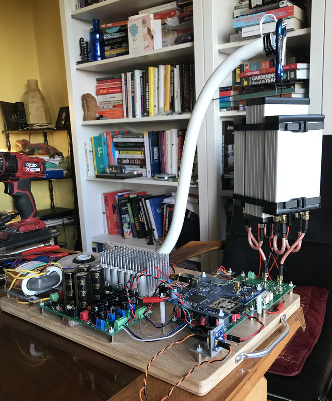
I have been running for about a week now the TWTMC Drixo-F 5.6448 & TWTMC Drixo-F 6.144 MHz finished boards together opposing one another in the long Hammond case.
The Frequency Doublers 5 - 11 & 11 -22 back to back in a small Hammond Case and the 6 - 12 & 12 - 24 back to back in another Hammond Case.
The doubler pairs in each case has jumper wires soldered between the power in points inside both Cases so that I need only one 16v In for the pairs.
I have left the Plastic rims on the cases as I am not needing continuity or perfect Faraday closures right now as i get to know these clocks.
I have used 100mm long SMA connectors throughout and managed to connect all up as you will see in the picture directly to the Sine to square switched output board with the group of Hammond Cases strapped and hung from an arm which gives it flexibility and support.
I know much of this implementation goes against much of what was discussed here but for me so far the result has been beyond expectations.
I have arrived at the final conclusion that Phase Noise is not a friend of any HiFi enthusiast with any sort of digital chain.
Each time i add a clocking solution with lower phase noise the impact is immediate and compelling and I tip my hat to Andrea for persevering on this journey.
It has made me a very happy listener of music with such flow, atmosphere and detail that I am humbled by the step forward these new clocks have made for me. Talking of percentage improvements or trying to describe how it enhances the listening experience is not something I believe can be quantified by me but if you ever get a chance to hear a system with and without you will know what i am talking about.
To finish a fantastic journey and worth the leap of faith it has been for many.
Last edited:
So far just running a 22.xxxx MHz clock with a Salas 16.5 V shunt power supply, sma cable into the squaring circuit to drive a McFifo re-clocker. The squaring board pulls power from the McFifo via the pins. Eventually I will add a doubler and the second time base. The ESS DAC is also being fed the master clock from a buffered output on the McFifo
Hello,
Looks very nice your bungee jumping clock circuitry.
Putting two frequency doublers in one box saves a lot of space.. If you need to reduce the number of boxes i think this would be the most logical choice..
It could be that i will go for two 61,7F supercaps in parallel connected .
A few lifepo4 contain more juice so to say. BUT if two supercaps can play for 4 ? Hours and in that go down from 17 to 16,2 volts and then be " recharged " up to 17 volts again in a short time. They can be charged an extreme number of times and if you have a beefy charger it can be done quickly.
I will offer Doede the possibility to test a pair of 61,7F caps with the clock circuitry.
Greetings,Eduard
Attachments
- Home
- Group Buys
- The Well Tempered Master Clock - Group buy