A quick update. I have one channel up and running. This has the IPS-VAS and OPS running on the same rails (30V in this build). I don't have the boosted 36V rails built yet.
Bias and DC offset appear to be very stable. DC offset ranges from 0 to 2mV during my tests and bias did not drift.
I'm running at 400mA of bias because this test is in a 100F (37c) garage, and it was too hot with 600mA. At 600mA, my heatsinks were 140F (60C). With a more reasonable 75F (24C) ambient, I imagine it would be OK.
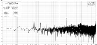
I attached some quick plots from REW. I'm still in the learning process with REW. This is from a Focusrite Scarlet 2i2 3rd gen. Not sure if the main's spikes are from my testing setup or just poor PSRR.
I gave a quick listed with one channel on my garage speakers... sounded good on those.
Now on to the second channel.
Bias and DC offset appear to be very stable. DC offset ranges from 0 to 2mV during my tests and bias did not drift.
I'm running at 400mA of bias because this test is in a 100F (37c) garage, and it was too hot with 600mA. At 600mA, my heatsinks were 140F (60C). With a more reasonable 75F (24C) ambient, I imagine it would be OK.
I attached some quick plots from REW. I'm still in the learning process with REW. This is from a Focusrite Scarlet 2i2 3rd gen. Not sure if the main's spikes are from my testing setup or just poor PSRR.
I gave a quick listed with one channel on my garage speakers... sounded good on those.
Now on to the second channel.
Attachments


Adding drivers will make a bigger impact than altering the vas. At least from my simulations. They reduce the VAS sensitivity to gain mismatch with the VAS. Which is an issue in the as-built design due to the current availability of KC3505D / KSA1381E.
Also, changing the VAS impacts clipping behavior. The single device VAS clips softly. Changing to a two device VAS sharpens it.
Distortion will drop, but the resulting distortion increases to higher order with more phase shift.
Drivers may also allow you to drive vertical MOSFETs with more current. This may be needed to drive their higher gate capacitance.
You’ll also want to assess thermal stability. A lot of sim time went into ensuring the as-built design was stable.
I got the boosted rails working. It's now running with 30V main rails and 36V IPS-VAS rails. Here are some new REW distortion plots. You may note that the dbfs levels read different. On my first tests I had a 100k/100k voltage divider in place. I was taking a quick read this time and hooked it up direct. In both cases, output was monitored on an analog scope to verify the output levels.
Boosting seems to make a big difference with distortion. Regardless of the actual levels, the composition seems to be largely 2nd order which is good. At 10k, its a mix of 2nd and 3rd. In both cases, higher order harmonics drop fast.
I still have the mains spikes though. I don't get these on a loopback test, so I'm thinking this is due to messy bench wiring. I suspect it will be reduced once its tidy and in a shielding chassis.
Attachments


A bit more progress on my REW measurements. I realized I didn't have averaging set. Adding this shortened the "grass". And I found most of the mains spikes was from my oscilloscope. I turned it off and it got much better.
However, the mains spikes that remain are present even with power turned off. I'm going to try cleaning up the grounding on the PSU and add a Ground Loop Breaker to see if I can clear it up.
Distortion profile still looks good though.

However, the mains spikes that remain are present even with power turned off. I'm going to try cleaning up the grounding on the PSU and add a Ground Loop Breaker to see if I can clear it up.
Distortion profile still looks good though.
I tidied up the PSU wiring and refined my REW skills a bit more. Here's the latest readings of 1kHz at 1W and 5W. Output of 5W is as high as I can go with this setup as the gain on this amp is only 15.5dB and REW only seems to be able to output 1Vrms.
The mains spikes are still there, but they are -100dB at 1W.
I'm pretty happy with the noise figure and the harmonic spectrum.
Time to build the other channel!
The mains spikes are still there, but they are -100dB at 1W.
I'm pretty happy with the noise figure and the harmonic spectrum.
Time to build the other channel!
Attachments


No, REW can output 100% full scale whatever your soundcard can deliver.REW only seems to be able to output 1Vrms.
Want to follow this thread...... Nice, simple design Lineup
Greetings to all.
Greetings to all.
This is my final Ultra.
Have added 2 potentiometers for DC-offset adjust. R2 and R15.
Changed compensation to 47pF.

Have added 2 potentiometers for DC-offset adjust. R2 and R15.
Changed compensation to 47pF.
what schematic did you end up building?10-4. Time to do some research to figure it out. I’m running a Focusrite Scarlett 2i2 3rd gen. Its spec’d at 15.5dBu balanced. 9.5dBu unbalanced should be capable of 2.3Vrms. In theory I should be able to drive it close to 25W with its 15.6db of gain.
What is a Slew Rate of amplifier?
Looks very good and simple design.
You can add CCS with Wilson Current Mirror at IPS so to lower excellent low THD, and add cascode into VAS to improve high Slew Rate and run faster output lateral mosfets.
Also adding bootstrap circuit you can run almost rail-rail output mosfets because you loose around 3,5VDC of headroom for output mosfets.
BIAS trimmer needs two more resistors before and after trimmer because trimers don't like to run more that few mA current of it.
Adding RC filter into rails will be very good with 1000uF/35V paralleled with 100nF MKP capacitor to improve ESR on electrolytic on high frequency.
Try these tweaks and you will be suprised how simulation improve.
Him mainframe99,what schematic did you end up building?
The as-built design is described in post 166. I discuss the goals of my version and the concept for the boosted IPS-VAS rails. I discuss differences from lineup's design in post 177, which also has some questions for lineup - he never responded.
lineup does not mention which gain grade the VAS devices are. This has an impact on the design. I would not suggest building his version unless this is addressed. Lineup's design in post 193 also lacks a feedback cap, and output networks. I would not suggest leaving these out. Without the feedback cap, DC offset will vary by 50mV to 100mV from hot to cold states. I've mentioned thermal stability before, but he never responses.
I attached the as-build schematic. Me and benpe both have working builds running. It is showing no signs of instability. DC offset and bias have very good thermal stability. DC offset holds on my build within 1mV.
Attachments


Hi ronovar,
Slew rate from simulations on as-built design is ±35 V/μs at 1 watt into 10kHz. It increases to +110/-50 V/μs at 25 watt.
I'm not sure I understand your comment on the bias trimmer. Adding a series resistor will not change the current. It will reduce dissipation, but the current flowing will still be the VAS current.
I don't understand what you're describing here. Can you elaborate? Also, mine and benpe's builds are running boosted IPS-VAS rails which does allow the MOSFETs to swing closer to the rails.
I don't see any need at this point to complicate the design with more active devices. The single device VAS in particular has benefits. It keeps the distortion lower order with less phase shift and clips softly. Going to a beta-enhanced or cascode VAS negatively affect this.
However, if I was going to add anything, it would be drivers. These have the single biggest impact in simulations, while maintaining the character of the design. They also allow you to ditch the feedback cap while maintaining thermal stability. And they reduce the impact of gain mismatch on the VAS devices, allowing KSC3503D/KSA1381E to be used.
What is a Slew Rate of amplifier?
Slew rate from simulations on as-built design is ±35 V/μs at 1 watt into 10kHz. It increases to +110/-50 V/μs at 25 watt.
BIAS trimmer needs two more resistors before and after trimmer because trimers don't like to run more that few mA current of it.
I'm not sure I understand your comment on the bias trimmer. Adding a series resistor will not change the current. It will reduce dissipation, but the current flowing will still be the VAS current.
Also adding bootstrap circuit you can run almost rail-rail output mosfets because you loose around 3,5VDC of headroom for output mosfets.
I don't understand what you're describing here. Can you elaborate? Also, mine and benpe's builds are running boosted IPS-VAS rails which does allow the MOSFETs to swing closer to the rails.
You can add CCS with Wilson Current Mirror at IPS so to lower excellent low THD, and add cascode into VAS to improve high Slew Rate and run faster output lateral mosfets.
I don't see any need at this point to complicate the design with more active devices. The single device VAS in particular has benefits. It keeps the distortion lower order with less phase shift and clips softly. Going to a beta-enhanced or cascode VAS negatively affect this.
However, if I was going to add anything, it would be drivers. These have the single biggest impact in simulations, while maintaining the character of the design. They also allow you to ditch the feedback cap while maintaining thermal stability. And they reduce the impact of gain mismatch on the VAS devices, allowing KSC3503D/KSA1381E to be used.
Surely a cascode VAS reduces VAS distortion considerably for all harmonics by removing Early and Miller-non-linearity effects, so "lower order" is spoiled by being "much more"? No VAS soft clips, that takes special circuitry and loses appreaciable amounts of headroom by necessity, and can't be done inside a GNFB loop.
The fairly common 3-transistor VAS configuration (VAS + cascode + current-limiter) is a top performer. More components is usually better performance when chosen wisely. A single transistor VAS is usually going to fry if the amplifier is overloaded too, its a fragile setup with limited performance and very demanding on the transistor used.
The fairly common 3-transistor VAS configuration (VAS + cascode + current-limiter) is a top performer. More components is usually better performance when chosen wisely. A single transistor VAS is usually going to fry if the amplifier is overloaded too, its a fragile setup with limited performance and very demanding on the transistor used.
Hi Mark,
I attached a plot of what I meant by soft clipping. Maybe not tube-like, but it does look "softer" than I've seen with other designs. And I was wrong about the cascode affecting this. I recall simulating different VAS configurations and seeing it negatively affected... maybe it was the beta enhanced VAS I'm thinking of. My mistake.
Regarding the impact of cascoding the VAS, I ran a quick simulation of 1kHz at 25W. Distortion drops, by half, but it's all even order reduction. You can see from the FFT plots that 3rd order it largely unaffected. Now I must point out that this was a quick sim. I didn't spent much time trying to tune it.
I think I would be more interested in how it might affect other factors. Such as:
- Device gain mismatches (an issue with the as-built design)
- Slew rate and slew rate symmetry (if that matters).
- Intermodulation distortion - this has not been assessed with the current design. It's something I struggle with in simulations.
Attachments


These FFT plots looks great,but need time to play with simulation.
The sound signature of amplifier is designed using IPS+VAS and output is just a buffer.
Here is schematic from apex for IPS and VAS example that will add 4bjt to IPS and give hybrid sound to amplifier (try to simulate using jfet as on your schematic and adding bjt ccs but replace zener diodes ccs with 2xbjt with red led to give lower noise ccs or you can use jfet for ccs to have high impendance load for ccs).
And then is cascoded VAS with voltage references that can be 1N4148s or hlmp6000 that is very low noise red diode.
Hybrid amplifier will sound like soft tube but needs tweaking in simulation.
I just give you a hint how to improve this nice circuit but i will not replay anymore because you have your way of optimizing amplifier that is very nice.
Keep that good work!
https://www.diyaudio.com/community/attachments/b2000-2-jpg.554795/
- Home
- Amplifiers
- Solid State
- Ultra Amplifier with JFET input and Lateral MOSFET out