 Trying to fix post which has stalled the thread.
^Edit->Copy raw SPL command is unlimited enabling for example max 1 GHz. Phase column has 0.0 because minimum phase extraction would require internal frequency range which is limited to 5-40k.
Thank you Kimmo.
I tried to use the calculate T/S parameter function, I just copied and pasted T/S parameter values from REW, and calculate, and provided impedance data exported from REW, the software poped up an warning message, even after I input BL information.
Do you know why?
Is the current error value O.K.?
Attachments

^R0=0 is not right and the reason why extended Z model solver refuses to start. Dual added mass method with sparse 1/48 oct. frequency steps is not necessarily very stable with very high Qms drivers. In that case I would use single added mass of 7 g if dual added mass fails.
I can try to get rid of R0=0 error if you send all three impedance responses by e-mail or attach to forum.
I can try to get rid of R0=0 error if you send all three impedance responses by e-mail or attach to forum.
^R0=0 is not right and the reason why extended Z model solver refuses to start. Dual added mass method with sparse 1/48 oct. frequency steps is not necessarily very stable with very high Qms drivers. In that case I would use single added mass of 7 g if dual added mass fails.
I can try to get rid of R0=0 error if you send all three impedance responses by e-mail or attach to forum.
Hi Kimmo
I've attached the impedance response data exported by REW. Are thses what you need?
Export settings:

Attachments
^Problem found. Magnitude and phase responses in impedance measurements do not match i.e. responses are not close enough to minimum phase which leads parameter solver to impossible situation.
See thin blue curve in attached file: measured free air phase response cannot rise towards 90 deg with that flat & shallow magnitude response. Or magnitude response cannot be flat & shallow at HF if phase response rises towards 90 deg. Phase response should be quite close to simulated cyan curve assuming that measured magnitude is more accurate than measured phase.
I added Ignore measured phase checkbox to program to get result, assuming that measured magnitude responses are okay. Parameters are solved by impedance magnitude responses only. Click 'LOG model' or 'Added mass' option few times if extended model solver does not give immediate result with error less than 0.200.
Attachments

Last edited:
^Ignore my previous post please 🙂 Actual problem was comma as thousand separator in impedance response files. Thousand separator is not allowed with VituixCAD. For example 20000 Hz must be either 20000.000 or 20000,000. Not 20,000.000.
So this new 'Ignore measured phase' is not needed to get result, but I will not remove the feature:
So this new 'Ignore measured phase' is not needed to get result, but I will not remove the feature:
Attachments

Thanks for the absorber change.
Re' TF button
After I got the hang of it, I was able to get better results using TF mostly from working on woofer time alignment but it didn't help with tap requirements.
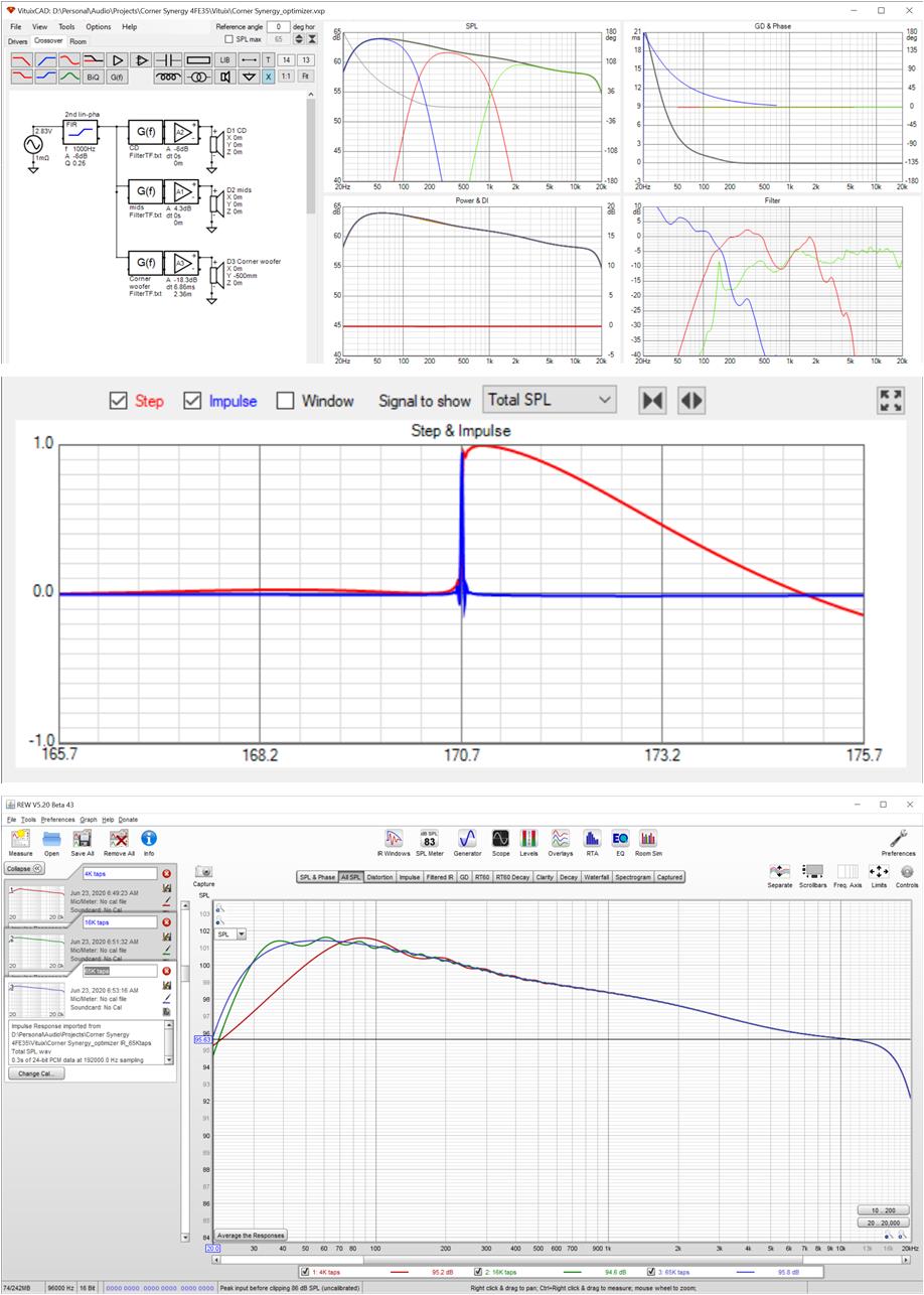
I imported IR(taps) into REW to evaluate. Doing this, I couldn't help but think how nice it would be if there were an (Save as Overlay) button right above the export button on the IR screen. The finite tap count FRs are plotted at 2 db per division so the error is not as bad as it looks
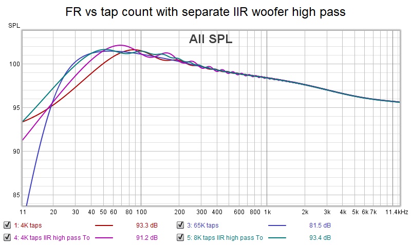
Taking the woofer high pass filter out of the G(f) and into a separate IIR block brought me about 1 db closer to the 65K tap curve in the 20-40 Hz region with 4K taps. 4K taps aren't quite enough; 8K looks great.
Very interesting !
As some DSP are tap limited, did you find a way to export an impulse with ie 1014 taps without the low end TF to avoid the woofer high pass definition limitation
Ie from 200 to 20khz, to use the exported FIR filter as xo .
Because if I don't put a high pass on woofer in Optimizer It results, logically, in a positive EQ 🙂 and that doesn't be defined enough with 1024 taps 🙂
Don't know if I'm clear enough 🙂
regards
Last edited:
Because if I don't put a high pass on woofer in Optimizer It results, logically, in a positive EQ 🙂 and that doesn't be defined enough with 1024 taps 🙂
I'm quite sure that this is not mentioned in user manual, and separate application instruction for creating IR file for FIR crossover does not exist. But I think we've had some discussion in this thread that HP slope of woofer's target response in Optimizer window should imitate woofer's natural HP slope, and Lin.pha should be unchecked to minimize taps by minimizing any EQ needs at LF. 1024 taps should be easily possible if the lowest XO frequency is high enough. Possible error happens at HP slope of mid-range driver.
One possible trick is using Pre-delay instead of Center IR in Impulse response window. Program does not have as many time base options as rePhase, but pre-delay could be better option if IR does not have much pre-ringing i.e. phase linearisation is done at mid...high only.
Thousand separator is not allowed with VituixCAD. For example 20000 Hz must be either 20000.000 or 20000,000. Not 20,000.000.
Build of 2.0.51.6 with workaround for comma as thousand separator uploaded few minutes ago: If data row contains one comma (assumed in frequency value >= 1000 Hz) and three dots, comma is removed to avoid error in frequency value.
This is really quick and dirty trick, but almost only way to support automatically also comma-separated files in addition to space, tab and semi-colon separated files.
I might have mentioned that localized exports are very unfortunate because txt, frd and zma files are data files in this scene and should have invariant culture formatting - just like values in xml files. Programmers should take care that their program does not export localized value formats in data files no matter settings in control panel of operating system. Otherwise this format mess will never end.
^Ignore my previous post please 🙂 Actual problem was comma as thousand separator in impedance response files. Thousand separator is not allowed with VituixCAD. For example 20000 Hz must be either 20000.000 or 20000,000. Not 20,000.000.
So this new 'Ignore measured phase' is not needed to get result, but I will not remove the feature:
Good job.
This kind of settings (Use computer's number format in REW export menu) is optional in REW, but I don't know which one is better just follow the sample picture settings in REW help file.
I encouter another problem, the "Delete rows" function is not working when I delete a speaker row in Enclosure window.

BTW, how can I estimate the value of Error in calculate T/S parameter window?
Use computer's number format in REW export menu
That could be good or bad. Better to select fixed global setting to make files interchangeable overseas i.e. 'REW export number format'.
I encouter another problem, the "Delete rows" function is not working when I delete a speaker row in Enclosure window.
Select full row(s) with row headers (gray squares on the left) to delete rows. Whole row in blue and then delete. Finally save local driver database.
how can I estimate the value of Error in calculate T/S parameter window?
That is squared error sum divided by count between simulated and measured impedance response. Very good match is about 0.05. Less than 0.2 is okay. Sometimes theoretical model does not match with reality no matter parameters. Then anything with gray background is okay because it's still acceptable to local database.
^Ignore my previous post please 🙂 Actual problem was comma as thousand separator in impedance response files. Thousand separator is not allowed with VituixCAD. For example 20000 Hz must be either 20000.000 or 20000,000. Not 20,000.000.
So this new 'Ignore measured phase' is not needed to get result, but I will not remove the feature:
I see your simulation plot and T/S parameters calculation value, the Error is only 0.05, looks very good.
I looks like you are using my uploaded impedance data,but I can't get the same result like you.
Sorry for my poor English, is there anything I didn't understand clearly?
Please check the process below, I just input Known parameters, and press calculate, Error value is 711.996 too high.
Re value in "Know parameters" should be input as the same one as voice coil DC resistance measured by me?

Thanks a lot for this software. I did design in the same procedure even without this information. It means, that it is quite intuitive and that is perfect.Simulate box & driver with Enclosure tool, export Total SPL, start Diffraction tool, design box and locate driver, select previously exported Total SPL to Half space response text box, check Full space, export and feed polar responses to main program with Directivity and Feed speaker checked. Abracadabra!
It's not direct but doable.
But next steps are not so clear, please explain...
I have made crossover design with driver frd/zma data I got from Diffraction tool. If I click on driver there are X(width),Y(height),Z(depth) values. What do they mean? They are relative offsets to ones I entered in Diffraction tool or I must set values (X,Y) the same as in Diffraction tool?
What is zero value? It is position of microphone I entered in Diffraction tool?
Thanks for answer.
I looks like you are using my uploaded impedance data,but I can't get the same result like you.
Solving of parameters is very close to lottery especially with Dual added mass + LOG model. Solver could find good result if initial values are good. That is not always the case so calculating initial parameters with (single) Added mass method or without LOG model or ignoring measured phase could help significantly.
Possible methods to restart solver with Dual added mass + LOG model:
a) click Added mass option and then click Dual added mass option
b) uncheck LOG model and then check LOG model
c) check Ignore measured phase and uncheck Ignore measured phase
Repeat until simulated responses match with measured.
Note! You don't have to use Dual added mass with LOG model if target is just to simulate box. Fancy T/S models have some significance in R&D, but common diyer does not need very accurate parameters for purchasing drivers and designing box.
Error value is 711.996 too high.
Parameters of Extended impedance model i.e. Le, Leb, Ke and Rss must be solved or entered to get small Error. Zeros give always high error.
Re value in "Know parameters" should be input as the same one as voice coil DC resistance measured by me?
Yes. Dual added mass method solves also Re, but it's good to know before parameter calculation.
Please download and install 2.0.51.6 again. The latest build has some improvements: Solver for dual added mass method starts with Qms=8.0, R0=0.3 and Re=4.0 when new driver is added. In addition, max. 9 automatic restarts added if error is greater than maximum (1.5). Should give acceptable result by entering Sd only - without manual restart tricks.
Last edited:
What do they mean?
Are you sure that you're asking something which is not explained in user manual and measurement instructions?
For example user manual for driver instances in crossover:
Each driver instance added in the crossover can be provided with location relative to “design origin”. Location is entered to Parameters grid. Design origin is typically perpendicular endpoint of listening axis on front baffle surface. X [mm] is horizontal coordinate of center point; negative to left and positive to right. Y [mm] is vertical coordinate; negative down and positive up. Z [mm] is horizontal distance coordinate; negative closer to mic and positive further from mic.
Horizontal rotation R [deg] and vertical inclination T [deg] of drivers are also supported. Rotation R [deg] is positive to counter-clockwise from top view, and inclination T [deg] is positive to up.
VituixCAD Measurement Preparations.pdf:
• Elevation of mic is at the center point of driver under test i.e. mic and driver have the same Y-coordinate in mm. Turn speaker back/front if front baffle is tilted.
Exception: Mid and tweeter can be measured at common mic elevation = average Y of center points if drivers are small and close to each other, baffle is straight (non-stepped) and vertical plane is not measured i.e. drivers are circular and hor/ver difference in baffle diffraction is ignored on purpose.
• Rotation center on X-axis while off-axis measurement sequence is at the center point of driver under test.
• Rotation center on Z-axis while off-axis measurement sequence:
a) Rotation center on Z axis is common for all drivers if drivers are installed in straight non-stepped baffle. Rotation center is typically on surface of front baffle for the tweeter. Z=0 mm for all drivers in crossover simulation regardless of difference between baffle surface and acoustical center.
b) Rotation center on Z-axis varies with stepped baffle. Drivers on each baffle level has own rotation center on Z-axis. Distance from each baffle level to microphone must be constant (1000 mm). Differences on Z-axis are entered to the simulator as Z mm of the driver, e.g. tweeter Z=0 mm, mid range Z= 20 mm, woofer Z= 100 mm.
Basically microphone position in Diffraction tool equals to speaker's origin in the main program. But usually microphone should be located at the center point of driver in Diffraction tool for exporting simulated directivity to drivers the main program because rotation center of driver's measurement data is specified to be center point of driver's radiating area on baffle surface.
Solving of parameters is very close to lottery especially with Dual added mass + LOG model.
Possible methods to restart solver with Dual added mass + LOG model:
a) click Added mass option and then click Dual added mass option
b) uncheck LOG model and then check LOG model
c) check Ignore measured phase and uncheck Ignore measured phase
Repeat until simulated responses match with measured.
Thank you Kimmo.
in step a , I just click Dual added mass option , and the values changing.
Follow your instructions, I get a good Error value like this. It's tricky, deep and interesting.


Do all these mean my measurement is good enough? and the T/S parameters are also good enough?
Note! You don't have to use Dual added mass with LOG model if target is just to simulate box. Fancy T/S models have some significance in R&D, but common diyer does not need very accurate parameters for purchasing drivers and designing box.
May be you are right.
I just want to make a good box for QS-216 speaker.
I even didn't know dual added mass method untill John the author of REW suggested me to try it in REW, cause it's more acurate than the old method.
Someone even uploaded the original paper of dual added mass method by Jeff Candy and Claus Futtrup to the avnirvana forum.
I found there is no air temperature value when calculate T/S parameters in VituixCAD, is it not important?
But now, if my measurement and T/S parameters are good enough, I will start simulating enclosure in VituixCAD.
Last edited:
It's tricky
Shouldn't be tricky at all with the latest build. Result at once by entering Sd. Also with LOG model and measured phase.
Do all these mean my measurement is good enough? and the T/S parameters are also good enough?.
...
I just want to make a good box for QS-216 speaker.
Evaluation of accuracy of measurements is impossible from here, but looks good enough. I'm also saying that designing "good box" producing good sound reproduction is usually something else than knowing exact T/S parameters and getting some textbook response in the simulation.
This kind of methods and tools for preliminary design help to get "controlled learning experience".
I found there is no air temperature value when calculate T/S parameters in VituixCAD, is it not important?
Nothing is really important in T/S and enclosure simulation imo 🙂 It's just for preliminary design and product selection. Do not offer truths or miracles.
No “Total SPL” line in my SPL graph in VituixCAD. Did I download a bad version?
I’m running v2.0.51.5 (the latest version), but the Total SPL line doesn’t appear on my graph (it should be a default). The frequency response for each individual driver appears no problem.
I’m not sure what’s wrong. I followed the checklist in the User Manual, then I uninstalled and reinstalled the program, but the issue still didn’t resolve. Any ideas?
- Home
- Design & Build
- Software Tools
- VituixCAD