However the Holo May stops in all cases reproducing at 20Khz which seems in this very case to be caused by digital filtering.
IIRC, Holo May dac was once described as using digital error correction to improve performance limitations of most discrete resistor dacs. If so, maybe the error correction can only work up to a certain frequency. In that case they might need to limit the output bandwidth.
Taking this into account, my feeling is that 90dB for digital reproduction is still acceptabe.
Mostly benign sounding noise masks a lot of low level grunge in phono reproduction.
Not so for digital. The low level grunge is quite audible to some folks. Also, digital noise from dacs tends not to be so benign sounding, unless perhaps it is well masked by resistor noise added in the output stage. Thus, for a low noise dac, I'm not sure what DNR is good enough. There is evidence some people under some conditions can hear quantizing distortion even if dither is properly applied (Frindel, 1997). To me it means 90dB is not enough. AES Conference Papers Forum >> Are We Measuring the Right Things? Artefact Audibility Versus Measurement
Last edited:
For me personally, the 86 dB(A) to 91 dB(A) that I get out of my valve DAC is more than enough.
Regarding dither, see
High-order dither listening test
which suggests that statistical moments higher than the second can be audible, which would mean triangular dither doesn't necessarily suppress all audible artefacts of quantization. Pity I made a methodological error, so the conclusions are not as hard as they could have been.
Last edited:
First attempt, I hope it works.Dropbox - 17. Ennio Morricone - The Trio (From 'The Good, the Bad and the Ugly')-6dB.wav - Simplify your life...
You could use dropbox or wetransfer, both freeware.
Did you add dither after having reduced the level by 6dB?
Hans
Dropbox - 17. Ennio Morricone - The Trio (From 'The Good, the Bad and the Ugly').wav - Simplify your life
To my understanding no dither is applied: Audacity>Effects>Amplify>-6dB
EDIT: I can see now it's only for listening not to download. Is this OK?
Last edited:

I got a distinct sonic advantage going from a 2nV/rtHz to a 0.9nV/rtHz opamp in the I/V position in my DAC. A much better portrayal of the acoustic space on recordings which surprised me a lot, given how low the noise already was with the 2nV part in.
The opamps were AD829 and LT1028.
Aren't you using extensive passive filtering prior to the I/V? As a result this can preclude the use of high speed devices such as the AD829 in favour of the considerably slower LT1028. The LT1028 has considerable appeal as notwithstanding the marginal improvement in noise. The open loop gain, CMRR and PSRR are extraordinary, that under circumstances whereupon the bandwidth is highly restricted forms of cause to understand the possibility of improved performance to the extent outlined.
Thanks Marcel.
Anyhow, with passive I/V you won’t have to bother about dithering because all noise will be generated by the amp behind the RC network, which may be a bonus.
Hans
How about an MFB stage instead of either a passive I/V or a straight connection from the DAC to the op-amp?
Attachments
Regarding dither, see
High-order dither listening test
which suggests that statistical moments higher than the second can be audible, which would mean triangular dither doesn't necessarily suppress all audible artefacts of quantization...
I believe that you are correct about triangular dither, Marcel. As I recall, to completely de-correlate the dither from the signal requires resort to, at least, a quasi-Gaussian PDF.
The most sophisticated option, which is almost never seen in practice, is to utilize a subtractive dithering scheme to recover the lost processing SNR.
Last edited:
With nonsubtractive dither, you can make the first n moments of the total quantization error independent of the signal by dithering with the sum of n independent uniformly distributed random signals of 1 LSB peak-peak. When you make more and more moments independent of the signal by letting n approach infinity, the probability distribution of the dither approaches a Gaussian distribution, but with a standard deviation that also tends to infinity.
That is, in practice you will have to come up with a compromise between the noise penalty and how many moments become signal-independent. Triangular dither is the n = 2 case.
That is, in practice you will have to come up with a compromise between the noise penalty and how many moments become signal-independent. Triangular dither is the n = 2 case.
Last edited:
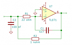
How about an MFB stage instead of either a passive I/V or a straight connection from the DAC to the op-amp?
Marcel,
That's a great idea.
I changed the values of the 100nF+4n7 into 9n+500pf to reduce the noise production from 5.4uV to 1.0uV for a single amp from 20Hz to 20Khz.
Not a big deal, but with the 100nF noise is rising exponentially above 20Khz.
Compare this to the conventional version that's producing 0.9uV for the same BW, but with a flat noise spectrum above 100Hz.
Still with the LT1468, I simulated the classical virtual gnd input version and the MFB version.
Image 1 below shows the signals at the virtual gnd input of both versions when offering a 18Khz+19Khz Fs signal sampled at 44.1K.
Quite obvious is the huge error signal reduction, almost a factor 30, completely preventing input saturation.
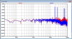
Also the spectra taken from both versions, conventional in red and MFB in blue with said input signal, is showing much less IM products for the blue version.
Hans
.
Attachments
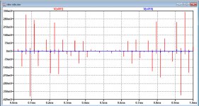
Hans Polak said:...Still with the LT1468, I simulated the classical virtual gnd input version and the MFB version.
Image 1 below shows the signals at the virtual gnd input of both versions when offering a 18Khz+19Khz Fs signal sampled at 44.1K.
Quite obvious is the huge error signal reduction, almost a factor 30, completely preventing input saturation.
Also the spectra taken from both versions, conventional in red and MFB in blue with said input signal, is showing much less IM products for the blue version.
Hans
Hans,
Have you tried simulating the classical virtual-ground transimpedance amp with a 9nF capacitor placed shunt, like C2 is located in Marcel's MFB schematic, to A.C. short the virtual-ground and the actual ground together? It would be interesting to know whether similarly minimizes the inverting-pin error signal produces largely equal results.
You can also reduce the ratio C2/C1, if you don't mind getting a more damped response.
That is, the fact that R2 C2 >> 1/(2 pi 20 kHz) is why you get the noise penalty. You solve that when you scale down both C1 and C2, but then the cut-off frequency gets very high. When you only scale down C2, the cut-off frequency doesn't become very high, but the response will be much more damped than the second-order Butterworth response that I chose.

- Home
- Source & Line
- Digital Line Level
- What do you think makes NOS sound different?