People who need the extended lifetime of polymers are willing to pay more. Polymers must use more expensive ingredients I reckon too, also perhaps production runs are shorter? Just guessing. I will certainly look at the prices of polymers on Taobao, despite not needing 20khrs life. Interesting that HZs are making something of a comeback - Mousers cap prices in general are extremely high.
That datasheet uses the authentic chip, such as the one available at Mouser TDA7297 STMicroelectronics | Mouser
Figure 9 in the datasheet 16.5v and 8 ohm speakers, was more helpful than an example with 4 ohm speakers. With 8 ohm speakers, it is 65% efficient (at max) and 2 amperes is enough. SMPS supplies put out worse quality when pushed to max, so we normally use them to half capacity, and then that's a 4 ampere supply.
Figure 9 in the datasheet 16.5v and 8 ohm speakers, was more helpful than an example with 4 ohm speakers. With 8 ohm speakers, it is 65% efficient (at max) and 2 amperes is enough. SMPS supplies put out worse quality when pushed to max, so we normally use them to half capacity, and then that's a 4 ampere supply.
Folsom TDA7297 amp is sweet
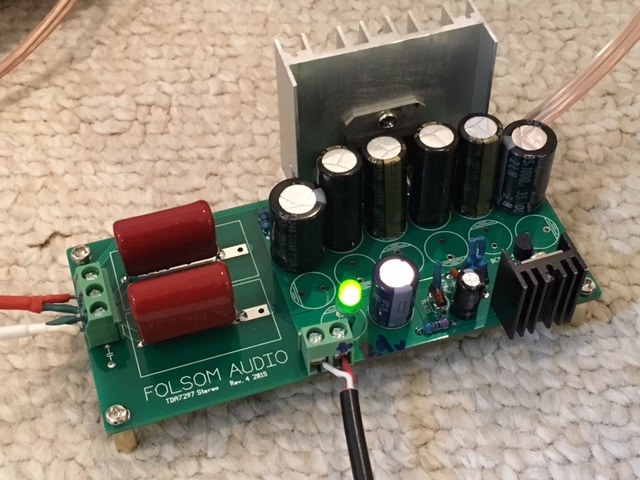
I just built up Destroyer OS' TDA7297 amp with some mods due to parts on hand. I am using four Panasonic FM 560uF 35v caps (measured 35mOhm ESR) and two Rubycon 1000uF 35v caps on the power rail. The TL431 shunt regulator is on order and in its place are two 9.1v zeners (measured as 18.45v across both) serving as the reference for the shunt regulator circuit that employs a BC337 and a TIP42 shunt transistor (substituted for the spec'd DH4511). The regulated output is 17.85v fed with a 24v 5amp SMPS brick. Shunt transistor is not too warm and working well. Main amp heatsink is stock unit from $5 Lunch Money amp so is rather undersized and toasty hot (8 seconds touch test). The TDA7298 itself was also donated from my lunch money amp. Desoldering all those pins was tricky")
The input caps 2.2uF 450v MKT's from CBB with 100nF 100v bypass film caps (underneath board).
I put screw terminal blocks on all connections for ease of use as temporary amp. I am listening to it with GR Research XL-S speakers right now and have to say that they sound excellent. Very nice mid range and clear top end. Bass is quite good with clean snap and tight articulation. I have to listen more to see how it compares to my discrete transistor class AB amps like FX8 or FH9. Silent when no signal present, no hiss, no hum. I think the SMPS might be a keeper on this setup. Not sure if a trafo and cap bank with matched Folsom "Antipole" PSU with CMC choke is necessary.
Thanks for the amp Destroyer OS!
I just built up Destroyer OS' TDA7297 amp with some mods due to parts on hand. I am using four Panasonic FM 560uF 35v caps (measured 35mOhm ESR) and two Rubycon 1000uF 35v caps on the power rail. The TL431 shunt regulator is on order and in its place are two 9.1v zeners (measured as 18.45v across both) serving as the reference for the shunt regulator circuit that employs a BC337 and a TIP42 shunt transistor (substituted for the spec'd DH4511). The regulated output is 17.85v fed with a 24v 5amp SMPS brick. Shunt transistor is not too warm and working well. Main amp heatsink is stock unit from $5 Lunch Money amp so is rather undersized and toasty hot (8 seconds touch test). The TDA7298 itself was also donated from my lunch money amp. Desoldering all those pins was tricky
The input caps 2.2uF 450v MKT's from CBB with 100nF 100v bypass film caps (underneath board).
I put screw terminal blocks on all connections for ease of use as temporary amp. I am listening to it with GR Research XL-S speakers right now and have to say that they sound excellent. Very nice mid range and clear top end. Bass is quite good with clean snap and tight articulation. I have to listen more to see how it compares to my discrete transistor class AB amps like FX8 or FH9. Silent when no signal present, no hiss, no hum. I think the SMPS might be a keeper on this setup. Not sure if a trafo and cap bank with matched Folsom "Antipole" PSU with CMC choke is necessary.
Thanks for the amp Destroyer OS!
Attachments

Last edited:
I have been listening to Melody Gardot's "Currency of Man" album on the Folsom Lunch Amp. Tracks "Morning Sun" and "Same to You" are exceptionally rendered with this amp. Wonderful bass that is deep, clean and articulate. Smooth vocals with great depth and body (if you know MG's voice you know what I mean). Fantastic amp - a winner! It definitely sounds way way beyond its lunch money origins and into hifi territory. The Folsom PCB indeed makes a difference and I wonder how much better it will be with a toroidal traffo and the Antipole linear PSU. I might have to buy a trafo just to find out.
I did make a few mods as described above due to circumstance, and it may sound even better with the TL431? But as you can see, in a pinch a couple of Zeners is not a bad thing to use as a reference in a shunt regulator. The TIP42 is also much more common and probably already in everyone's kit. The BC337 was included with my board so I almost went searching for an equivalent. I would have used 2N5401 if I did not have the BC337 on hand. Also, the 560uF 35V Panasonic FM's measure almost as good as the SEPF OSCONs from an ESR standpoint (especially if you have many in parallel) and they save quite a bit of $.
Good job Destroyer OS - I can highly recommend this amp.
Here are the songs (I have the CD):
https://www.youtube.com/watch?v=Yqf9TUNMLdo
https://www.youtube.com/watch?v=Jb3lTVL7qM8
Last edited:
I have to listen more to see how it compares to my discrete transistor class AB amps like FX8 or FH9.
Any further thoughts/impressions on this?
Any further thoughts/impressions on this?
I really like DOS's Folsom TDA7298 amp - it's amazing what a makeover can do for a very humble chipamp scavenged from a $5 amplifier. This thing is keeping it's own with my bigger hand-made class AB amps. It is power limited to probably 25w so at higher volumes, the other amps win, but within the operating range it was designed for, it has a very clear and dynamic presentation - with perhaps a little bit of exaggerated highs in the 5k to 7k range. The bass is quite amazing actually and very tight - good driver control with. I wonder if that is the MKT input cap and switching to MKP may tone that down a bit. The on board shunt regulated power supply really does clean up the sound and perhaps gives this amp lower noise (when inputs are off) than my bigger amps which have unregulated toroidal transformer based PSU's. Note that I am running this with a SMPS then it goes through the on-board shunt regulator which drops it from 24.5v to 17.85v. There is quite a bit of heat burned off - but that heat is regulated and keeps the rail flat. The level of hiss and hum leaking through this amp is almost zero. Overall, an excellent amplifier and well worth the very little effort to build as it is dead simple. I would not be afraid to use this amp on my best speakers. Again, I highly recommend this amp - you should try it. The Folsom PCB design does make a huge difference as you cannot get this sound quality with the stock lunch money PCB with mods.
Last edited:
Hi folks, I'm back!
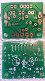
I've played around with a vintage amp I recently acquired, and now back to my lunch amp. I had a custom PCB made, as discussed a few pages back. I started populating the board and would like to ask some suggestions.
- I use 1uF MKP as input cap
- Small cap is 15uF electrolytic
- Should I place a jumper in place of the diode and leave the ceramic cap slot empty?
- Power cap, I have 4700uF 25V and 2200uF 50V laying around. Is there any preferable order of installation, maybe the bigger cap placed closer to the DC input, or else?

Thank you in advance!
I now prefer a 100uf instead of 15uf. No turn on noise.
It doesn't matter which cap is closer. But you'll need more capacitance off board for better performance. 12kuf isn't enough even, as I discovered.
BTW 1.5uf input caps will give proper bass, 1uf will be shy.
I hope you have correct ground paths. If you have any turn on problems it'll probably be if the SG and PG pin's aren't connected at a proper location.
I now prefer a 100uf instead of 15uf. No turn on noise.
It doesn't matter which cap is closer. But you'll need more capacitance off board for better performance. 12kuf isn't enough even, as I discovered.
BTW 1.5uf input caps will give proper bass, 1uf will be shy.
I hope you have correct ground paths. If you have any turn on problems it'll probably be if the SG and PG pin's aren't connected at a proper location.
So for whatever reason there's no sound coming out of that PCB that I had made. I tried consulting the designer and he guided me thru to troubleshoot it. Still no avail. First time I tried firing it up, the LED is not even lit up. I tried reversing the legs and it came to life. But there's no sound. I removed the 3.5mm socket, and tried touching the input cap pin with a screwdriver, and there is a noise coming out of the speaker. He suggested maybe the chip is dead, so I tried switching the chip with a stock lunch amp that I have. Still no sound out of the custom board, but the lunch amp is working just fine.
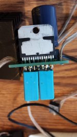
I wanted to hear some music out of this chip, so I just played some more with the lunch amp. Removed the ceramic cap, bypassed the diode, removed the terminal block and soldered wires directly. I also installed insulator on the chip.
I have a better 1.5uF MKP that I put on the custom board, so this cheapie 1uF gets a new home. The 1.5uF is JFX brand, rated at 5% and they do measure within tolerance. These yellow ones though, measured around 0.85 and 0.78.
The amp sounds fuller with these simple mods, but very noisy and very bad turn on noise. I don't have a 100uF cap but do have 47uF, and it immediately brings both kinds of noise down. Would 100uF brings floor noise down as well? If so, I'll definitely replace that.
Volume pot, the stock one is aluminium coated plastic, and gives noise when touched, so I replaced it with plastic Jazz Bass style knob, and it works well in that regard. Last touch is the LED, the stock blue is way too bright, this new white is softer and looks nicer. I'm happy for now.


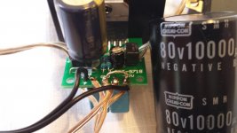
I thought I would share the mods I made to a lunch money amp. I used an unassembled kit and bought the TDA7297 chip, PH426 1.5uf and the MKP1837 .022uf bypass cap from Mouser. I was able to fit the PH426 to an enlarged holes in the board on the clip leg and the other end to the inputs. I put the bypass cap in the original location designed on the board for the input caps. I also followed Destroyer OS's recommendation on tying the signal ground and power ground when it comes in the board. I had to cut the trace on the board where it was joined under the chip. I first built a modded board with cheap components and it sounds good but gets warm, the Mouser chip runs much cooler. I'm only running a 12v 5a power supply. On the board I have a 2700uf power cap and off the board a 10,000 80v cap. I used a 100uf for the mute cap. I used a big heat sink from an Intel 370 processor chip. The sound of this board to newbies ears is just amazing. I am hearing female vocals and string instruments and all the quiet things I never noticed on other amps. I like this better than the 3116 for tone and I do know the speaker I have might be well suited for this amp. I have a Karlson K15 with a Goodmans Axiom 150 MK2 full range with whizzer cone, 15 watt and 15 Ohm. Thanks to all who helped with this fun project especially Destroyer OS. It might be time for me to buy his board, these huge components on this tiny board looks silly. Here are a few pics.
Attachments
You probably need to connect the signal and power grounds on your new board to get it to turn on.
Does that mean putting jumper wire from signal ground to power ground? If I take some pictures would you kindly tell me what to do? Sorry I have some ideas how to do this but since I have no solid background in EE I may ruin everything with on mistake. Might as well ask for detailed instructions. Thanks so much for your assistance!
- Home
- Amplifiers
- Chip Amps
- What the heck? It's less than lunch!