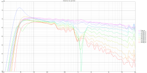
^how long gate did you use converting IR to FR? humps at 600 and 800Hz seem like reflections from something.
ps. nice, minimal baffle and very good waveguide, I don't see any diffration 😉
ps. nice, minimal baffle and very good waveguide, I don't see any diffration 😉
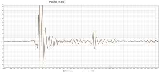
I don't use REW myself, can't help with the specifics, but the left edge of the time window should be always rectangular, otherwise you risk gross errors. It's best to see the actual window plotted in the IR graph (HOLMImpulse seems still unsurpassed in this regard).I wasn't sure where to set the gating.
Last edited:
Kimmosto recommends using Tukey 0.5 windows, as it provides better tracking with (true) nearfield or ground plane response. He posted a comparison somewhere, but I don't have it at hand; only an excerpt from VituixCAD manual.This is what I used for the REW files imported into VituixCAD. I wasn't sure where to set the gating.
View attachment 1191545
View attachment 1191546
Your left window is too short, it need to include full impulse. Increase from 2 to 4 or 5 ms. Right window is OK, can be increased from 12 to 13 ms.
REW does it too, and more: it shows you FR in real time as you drag windoow cursors.It's best to see the actual window plotted in the IR graph (HOLMImpulse seems still unsurpassed in this regard).
IMO, with recent updates it has surpassed all other measurement software, you should really try it.
Good to see that. Of course if you include the full impulse with a sufficient time margin before it actually starts, the shape of the left window edge becomes virtually irrelevant. But you must be sure this is the case.
"it shows you FR in real time as you drag windoow cursors" - yeah, that's was the great feature of HI for years. It's great that REW does it as well now, it's really extremely useful.
"it shows you FR in real time as you drag windoow cursors" - yeah, that's was the great feature of HI for years. It's great that REW does it as well now, it's really extremely useful.
No, the IR start is set at -0.651 (and that does seem to be at the big negative spike) while the left window is set to 2 ms.
Left window should indeed be increased, I can't see where the start of the impulse is as the window is zoomed in too far.
Well, an impulse always starts where it starts to deviate from zero...I can't see where the start of the impulse is ...
How many zeros are included before the start is irrelevant. (It can affect calculated phase (delay) though - that depends on how it's implemented. Here it seems that the time reference for where the IR actually starts can be set independently of the window.)
Last edited:
The pulse starts at -0.651 but the pulse is windowed between 2 and 16?No, the IR start is set at -0.651 (and that does seem to be at the big negative spike) while the left window is set to 2 ms.
Left window should indeed be increased, I can't see where the start of the impulse is as the window is zoomed in too far.
//
Well, an impulse always starts where it starts to deviate from zero...
Except when the recording devise isn't particularly clean itself.
So it should be fine.Nope, the widow to the left is 2 ms, the window to the right is 12 ms.
Yeah, but that shouldn't affect the calculated DUT response much. One doesn't have to be absolutely precise anyway - what's criticial is to have it consistent time-wise for all the drivers in the system. But in absolute terms, it doesn't really matter.Except when the recording devise isn't particularly clean itself.
Last edited:
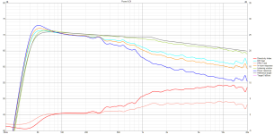
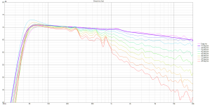
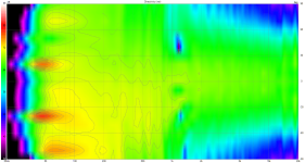
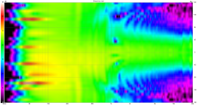
Now we are back at the Circle of confusion. One just can't avoid the thought whether a device that would stay flat on-axis but with the same power response slope wouldn't be actually better. You are in a position now where you can "easily" try both. That would be quite an experiment!Here are non-normalized polars when applying the crossover that sounds best to me so far with the simple freestanding R-OSSE.
Horizontal
View attachment 1191504
Vertical
View attachment 1191512
(BTW, I don't say it would be better, I just don't know. There are good theoretical arguments for either.)
Yes, I'm starting to understand that 🙂 - thanks!Nope, the widow to the left is 2 ms, the window to the right is 12 ms.
//
Freestanding 46 degree B&C DE111 R-OSSE over an 8 inch Dayton DC200-8 in a 9x9 inch enclosure. Waveguide can be moved up and down to find the best center-to-center distance relative to crossover.
View attachment 1191223
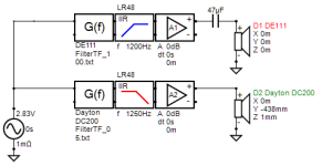
I don't know how to make crossovers. I'm learning in VituixCAD. I create the crossover then export it to Equalizer APO. That allows me to hear the crossover changes immediately. I'm listening to high order crossovers to get a feel for it then I'll back off to lower order crossovers more suitable for passive designs.
View attachment 1191224View attachment 1191225
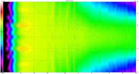
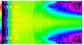
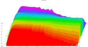
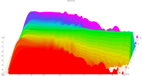
As expected, waveguide performance matches the simulations.
View attachment 1191226View attachment 1191227
I've listened to stereo music and watched a movie using only one speaker as a center channel. Music is very good but I'm most impressed with how well it works as a center channel for dialog intelligibility.
That's some serious dedication to getting good measurements :O
Wait, I didn't get good measurements. I used acoustic time reference because I don't have proper testing equipment and I didn't make sure each driver measurement was the same distance between the microphone and the acoustic reference. Apparently, when I moved the microphone to the next driver I was supposed to make sure the distance between the mic and the acoustic reference was the same. Plus, I don't understand gating.
3rd equation exists specifically for use with optimizer,in order to direct the optimizer results, you will find some description along these lines in the help file.
It's nice to see someone utilizing the transfer function block and impulse response convolution. It can be quite a powerful tool to develop active crossover using a PC as the DSP. You may have already found, but the frequency range and target slope should be carefully selected to avoid over-correcting the natural driver rolloff at low frequencies for example. As well, it can be useful to apply some smoothing to the driver response to avoid over-correcting every small little wiggle. Just use the smoothing options in the driver tab for this.
Your photos in the OP are a bit confusing, but the most important part of using acoustic timing reference is that the distance from the acoustic reference to the mic must remain constant for all measurements. This can be a bit challenging when moving from measuring the woofer response set to the tweeter response set, to keep precise distance from mic to reference. If you continue with further speaker designs, I would highly recommend XLR mic for electrical timing reference, you will find it a lot easier and reliable than the acoustic reference.
Also, by all means continue with near field and merge process, it's just 1 more measurement and a diffraction simulation, easily done to complete the woofer response.
Now we are back at the Circle of confusion. One just can't avoid the thought whether a device that would stay flat on-axis but with the same power response slope wouldn't be actually better. You are in a position now where you can "easily" try both. That would be quite an experiment!
(BTW, I don't say it would be better, I just don't know. There are good theoretical arguments for either.)
Do you mean listen to the difference between Variant R2 and Variant R7?
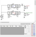
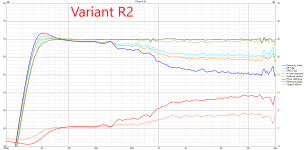
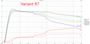
I exported the crossovers and EQ with the VituixCAD Impulse Response window. After you have all the variants (WAV files) in the Equalizer APO folder you can quickly switch between them in the config file. They all sound good to me. I prefer R7 because it sounds more accurate - to me - but I'll have people with better ears listen and compare.
I watched a movie called Chevalier (2022) last night on Variant R7. Left, Center, Right speakers but I have the DE250 on the center channel while using DE111s on the left and right. It sounds good. The DE250 had the inferior polar pattern due to diffraction off the large compression driver but I didn't notice. I wasn't as concerned with special effects as much as dialog intelligibility. The R-OSSEs have extremely good intelligibility. Dead easy to understand what the actors are saying.
I meant two versions of the waveguide, both with the same power response as you have now with your preferred version, but the second waveguide with flat on-axis response (i.e. more rising DI by that amount).
By setting different EQ you only change the overall tonality, but with those two versions you would change the tonality of the reflections against the direct sound - probably a lot more subtle effect, if at all noticeable (but maybe not). That would be the most interesting part.
By setting different EQ you only change the overall tonality, but with those two versions you would change the tonality of the reflections against the direct sound - probably a lot more subtle effect, if at all noticeable (but maybe not). That would be the most interesting part.
Last edited:
- Home
- Loudspeakers
- Multi-Way
- Acoustic Horn Design – The Easy Way (Ath4)
