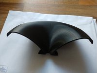
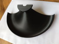
^ I trust you, never tried the new script. Trying to put together collection of memories how the OSSE script behaved and I was not able to make the narrower dispersion as nice for example. Perhaps the end results are similar with the previous and the new script and it was just hard to achieve with the parameters available. I never had automation to go through all the variations.
Narrow dispersion is indeed much harder than wide, considering all the real-world limitations.
For me it works well just to start with something reasonable and let the values change in some percentage (the sensitivity is not the same for all parameters). Typically the coverage angle is not something that would be left completely free.
For any optimization process the initial guess is very important but can also be a trap (local minimum).
Since people are showing large WG, here is what I have done:
Tool: Matlab GA + Ath + ABEC
50generations x 100individuals in about 3h15min with +/-50% on the 11 variables starting with the 260
If anyone has a simple approximation of the DI of piston on a cylinder I would be interested...
I would only question the woofer DIs shown, that doesn't seem very realistic to me, but I don't have any other model at hand (definitely it should be a woofer in a finite baffle, full space). That's easy to prepare in ABEC/AKABAK and I agree that would be a useful series of plots, adding to the overall picture.
The good thing about all these designs is that the DI is smoothly decreasing all the way down so matching a (any) woofer is never a problem, so long as the driver is capable of being crossed at the matching frequency.
The good thing about all these designs is that the DI is smoothly decreasing all the way down so matching a (any) woofer is never a problem, so long as the driver is capable of being crossed at the matching frequency.
Last edited:
^^ You could exploit VituixCAD diffraction simulator to generate some DI graphs. Not sure if it can do what you are looking for but here is few examples, DI magnitude (red line) for both in the text files. This is ~15" piston on 2m tall cylinder, Sd 880cm2. The other one is impossible (flat disk on curvy surface) and the other has the disk at flat surface and then huge roundovers. Not much difference where the crossover would be though.
Attachments
Last edited:
I already made some woofer simulations - https://www.diyaudio.com/community/...-design-the-easy-way-ath4.338806/post-6727218
(and also https://www.diyaudio.com/community/...-design-the-easy-way-ath4.338806/post-6727241 )
Matching to a woofer should never be the biggest problem, IMHO (no problem at all, actually).
(and also https://www.diyaudio.com/community/...-design-the-easy-way-ath4.338806/post-6727241 )
Matching to a woofer should never be the biggest problem, IMHO (no problem at all, actually).
Last edited:
In some ways R-OSSE parameters can still be understood with the set of important parameters of the previous release: s, n, k, and coverage angle, and q being a modifier to s. The new set of m and b are working in the domain of s now, giving more and complexer control and q has changed its function slightly, even if it is basically still controlling the steepness of s.In an attempt to get a feeling for what I'm looking at and what the different variable in the R-OSSE do, I plotted the reference (posted a few posts above) and +/- 10% for the k, m, r, b, q parameters.
What is good? What is bad? How do the results depend on the shape?
So the new abilites can be investigated in the relationship that m, b and q offer. Apart from this I would assume that a sketchy table that I had worked with is still saying something usable:
In which the effects of s in low frequencies ("LF") is understood as narrow-banded, of n (LF, again) as broadband, k effecting the loading between 5 to 10 kHz, traded in against linear distortion. All share the same area and therefore compete. N is effecting both the transition form throat (k) to walls as well as walls to mouth (s), so bigger changes in the ratio between s and n will also influence what can be done with k. Often one will find something that maiky76 has called 'local minimum'.
Especially to linearize HF behavior, I found it useful to start with a too-wide pattern, which was set up with a significantly wider than intended nomimal coverage angle, which was then "filled in" with the parameters s, n, q, k until a linear pattern was achieved, only to narrow it down afterwards. This flattened out the peak which otherwise would appear between 5 to 10 kHz with more loading applied by parameter k.
The good old OSSE formula is still the only option for a baffle-terminated waveguide. In a case of a free-standing one, the R-OSSE should be a lot more transparent in what it does. With the old algorithmic rollback in Ath, once the rollback starts (position set with 'Rollback.StartAt') the only thing that matters is the remaining length along the curve without the rollback, no matter what are the parameters (i.e. the rollback starts with the curvature at the chosen point and increases the curvature from that point with a chosen rate, until the remaining part of the underlying curve is "consumed")...
q should be definitely >= 1. The example shown is what happens for q close to zero.I just ran my first batch last night. Unfortunately quite a lot are totally rubbish:
View attachment 1025993
I'll try to come up with some boundaries for the parameters; unless someone already has done that...
(The higher the q the more the profile clings to the corresponding OS curve near the throat.)
Also there's no much sense for m < 0.5 or so (a typical good value will be around 0.8).
Last edited:
Last edited:
First of all I would like to Thank #mabat for the selfless sharing of knowledge and great contribution of the DIY community. The following measurements are the work of his research.
All measurements are performed with Tymphany DFM-2535R00.
Also I have BMS 4590 2". I would like to try to build "End game" combo with 15" woofer.
Any ideas for WG?
REW files you can find in links below, so you can play 🙂
https://drive.google.com/file/d/1GImZETlKzAOpmDzhJoGrPyE19Y5Rj-Hp/view?usp=sharinghttps://drive.google.com/file/d/1yMDZ3UoSbuXVtSomP8dLRjhcIZwLxbmP/view?usp=sharing
Impedance data:
https://drive.google.com/file/d/1ewcZIsDVt9XGKwI9sZeiBTib1e4BF4te/view?usp=sharinghttps://drive.google.com/file/d/1aUDe6r8SMbmfdKygPlVMBDQvP79f_3C0/view?usp=sharing
Measurement equipment, PC/REW-Khadas-TPA3118 20db gain-Umik1. Distance 1m
ST260+Tymphany DFM-2535R00
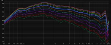
Psychoacoustics smoothing
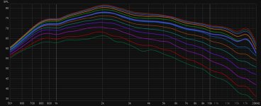
CT360+Tymphany DFM-2535R00
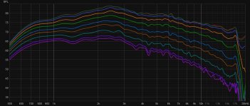
Psychoacoustics smoothing
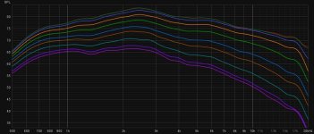
Measurement of CT360
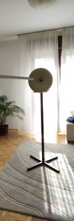

Measurements of Eminence Deltalite 2515+ST260+DFM-2535R00
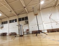
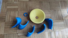
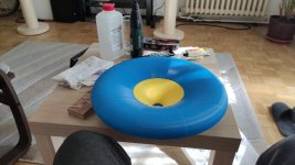
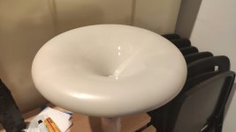
Build of CT360
All measurements are performed with Tymphany DFM-2535R00.
Also I have BMS 4590 2". I would like to try to build "End game" combo with 15" woofer.
Any ideas for WG?
REW files you can find in links below, so you can play 🙂
https://drive.google.com/file/d/1GImZETlKzAOpmDzhJoGrPyE19Y5Rj-Hp/view?usp=sharinghttps://drive.google.com/file/d/1yMDZ3UoSbuXVtSomP8dLRjhcIZwLxbmP/view?usp=sharing
Impedance data:
https://drive.google.com/file/d/1ewcZIsDVt9XGKwI9sZeiBTib1e4BF4te/view?usp=sharinghttps://drive.google.com/file/d/1aUDe6r8SMbmfdKygPlVMBDQvP79f_3C0/view?usp=sharing
Measurement equipment, PC/REW-Khadas-TPA3118 20db gain-Umik1. Distance 1m
ST260+Tymphany DFM-2535R00

Psychoacoustics smoothing

CT360+Tymphany DFM-2535R00

Psychoacoustics smoothing

Measurement of CT360


Measurements of Eminence Deltalite 2515+ST260+DFM-2535R00

Build of CT360


Congratulations to the assembly and finishing of the CE360, you're a brave man. It came out marvelously. 👍
The DFM 2544 measures well and sounds great on the various waveguides I've tried.
I would expect it to perform very well on your designs.
I would expect it to perform very well on your designs.
What was it with the DFM-2535R00 again, will it come back or was it cancelled permanently?
Nice surface, how did you treat it?
Nice surface, how did you treat it?
I have heard ATH is a great tool for designing horns. But I have a special need: To design a "Bullhorn". As far as I can see this is not supported by ATH. Seems to cover conical and exponential horns, not the folded structure of a Bullhorn. Can you confirm this? Thanks.
- Home
- Loudspeakers
- Multi-Way
- Acoustic Horn Design – The Easy Way (Ath4)


