thanks for sharing. I'll remove these 4 resistors. I'll have to bridge them, isn't it? i guess there wont be current if i dontthanks claude!
i went ahead and removed the 4 resistors as indicated by aiyimas first suggestion
i'm now getting 16.1-17Vrms of CLEAN output (depending on how nit pity you want to get)
from 17 to 20.4Vrms the top of the waveform gets a little wiggly as we hit clipping right about 20.8Vrms (identical to the rev 2.1 board)
so a nice improvement
so we went from 12.8Vrms with 2Vrms input (unable to clip with most DACs) ~20W@8ohm
to
17Vrms ~36W@8ohm of clean power, only requiring 1.1Vrms input, which most if not all DACs can achieve!
pushing it, you can go to 20.4Vrms ~55W@8ohm with 1.35Vrms input, which again, is achievable by most if not all DACs before things head to clipping
now, the rev 2.1 board stays clean the entire way to clipping to 20.8Vrms, so the rev 2.1 board is still superior for sure
provided some pics of the upper end of each of them

thanks for sharing. I'll remove these 4 resistors. I'll have to bridge them, isn't it? i guess there wont be current if i dont
no, you can simply remove them
i too have the new board, they are now shipping the rev 3.1 board (hidden under the larger heatsink) vs the rev 2.1 board that got so much praise. i have the black rev 2.1, so i have a good one to compare both units
this is what i've found
when i reached out to aiyima, this was their response
they also said "If two removed resistors are replaced in this position, the sensitivity will increase again by 1.8 times" with this picture
Hi Datrumole.
Now that you have a contact within Aiyima I wonder if this would be a good opportunity to ask them if they would share the Circuit Diagram so we can make modifications from a point of knowledge rather than "Trial and Error".
The A04 still appears to have loads of potential if we could get to the guts of it !!
.
.
i'll see what they will do
And I would also like to find out from Aiyima the name of the unnamed chip.
i'll ask
I got problem with my A07 - It has loud buzz when source is turned off (PC with soundblasterx) when you turn pc on its gone.
Also i have been reading alot about this amp and im so confused by some mods. It would be awesome if someone listed mods with what they do list like parts needed etc. For noobs like me.
Also i have been reading alot about this amp and im so confused by some mods. It would be awesome if someone listed mods with what they do list like parts needed etc. For noobs like me.
Hi
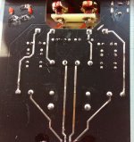
I have been playing about with cheap Chinese class d amps and modules during lockdown and recently acquired the Aiyima A04 revision 3.1 amp. Like others on this thread I have been a little dissappointed in its meagre output. Having read about Aiyima’s suggested resistor mods I opened up the casing to see how easy it would be for a complete novice like me to achieve. Looking at the underside of the board, build quality looks a little scruffy and there seems to be a damaged track (see attachment). Is this something I should be worried about? Thanks for any advice.
I have been playing about with cheap Chinese class d amps and modules during lockdown and recently acquired the Aiyima A04 revision 3.1 amp. Like others on this thread I have been a little dissappointed in its meagre output. Having read about Aiyima’s suggested resistor mods I opened up the casing to see how easy it would be for a complete novice like me to achieve. Looking at the underside of the board, build quality looks a little scruffy and there seems to be a damaged track (see attachment). Is this something I should be worried about? Thanks for any advice.
Attachments
The solder on those traces isn’t “reducing resistance” — the most sensitive ohmmeter on the planet couldn’t measure a difference between that partially soldered trace before and after adding more solder on top of it.
The solder is there to prevent oxidation. I know this is an amateur hobbyist board but sometimes misstatements call for correction. No offense intended.
The solder is there to prevent oxidation. I know this is an amateur hobbyist board but sometimes misstatements call for correction. No offense intended.
No drama, it will play music, but indeed the additional solder that is supposed to reduce the resistance isn't there as it should all the way.
Means not great, if you can add solder all the way as they did to correct where it is lacking.
Reduces resistance, gives bigger traces that can easier cope with more current / Amperes, reduces oxidation indeed as can be seen in the pix... call it what you want, I made it easy and the bottom line is "no harm to address it".
While at it, I find all traces really thin on this board considering what output power they claim, but well, I like it big
But I don't own this unit and I am out of it since ages, so have fun guys, and let us know if you find a nice tweak that hasn't been posted, always a welcome addition...
Claude
While at it, I find all traces really thin on this board considering what output power they claim, but well, I like it big
But I don't own this unit and I am out of it since ages, so have fun guys, and let us know if you find a nice tweak that hasn't been posted, always a welcome addition...
Claude
Last edited:
Yeah, not really, no. Debates are the lifeblood of amateur hobbyist forums, but this is not a debate, it is something professionals know not to be true and amateurs pass between them as “you have your truth and I have mine”. Well no, there is objective reality, and the objective, long-settled reality is that adding solder to an already-oxidizing trace on a board that left China months before you got it does not and can not reduce resistance, increase current capability, or reduce oxidation. If it makes you feel better because you “like it big” I recommend never telling this to an actual audio professional from whom you wish to be taken seriously.
One if the first things I learned as an apprentice engineer is that solder should never be used as a signal-carrying conductor. It is merely a fast-setting “glue” that holds in place a sound mechanical connection. Solder is conductive because it’s helpful to have contact points in a circuit to measure voltages when troubleshooting, not because solder is meant to be an actual signal carrier.
The second thing I learned is if you can easily pull apart a mechanical connection before you solder it, it is not ready to solder. Mechanical integrity — metal pressed tightly against metal — is the signal path. Solder is just there to make sure the metal-to-metal connection doesn’t separate over time due to vibration, heat, or a long and bumpy boat ride from China.
If your audio signal is passing through solder you’re doing this wrong.
Reduces resistance, gives bigger traces that can easier cope with more current / Amperes, reduces oxidation indeed as can be seen in the pix... call it what you want, I made it easy and the bottom line is "no harm to address it".
While at it, I find all traces really thin on this board considering what output power they claim, but well, I like it big
But I don't own this unit and I am out of it since ages, so have fun guys, and let us know if you find a nice tweak that hasn't been posted, always a welcome addition...
Claude
Mate, I am an engineer and actualy quite a bit more. I won't debate with you: you posted your absolute truth, so be it, the 4 posts you posted in 8 years (facts) give me the picture and I have no time for you.
For the others: this is a proposed fix, not the ideal situation where of course we wouldn't have solder in parallel to paths or whatever because it wouldn't be required first place. And, fact is more conducting section means more current capability, whatever, eventhough I don't like to parallel lines but that's another debate.
I am off, no time for this
Claude


Mate, I am an engineer and actualy quite a bit more. I won't debate with you: you posted your absolute truth, so be it, the 4 posts you posted in 8 years (facts) give me the picture and I have no time for you.
For the others: this is a proposed fix, not the ideal situation where of course we wouldn't have solder in parallel to paths or whatever because it wouldn't be required first place. And, fact is more conducting section means more current capability, whatever, eventhough I don't like to parallel lines but that's another debate.
I am off, no time for this
Claude
Well said Claude.
Don’t give up on the rest of us - I have always both valued and enjoyed your contributions and still actively playing with both The Aiyima and 3e-Audio amplifiers. Just building some of the BTSB Buffer Boards from XRK Audio to use as a front end.
James
.
.
Don’t give up on the rest of us - I have always both valued and enjoyed your contributions and still actively playing with both The Aiyima and 3e-Audio amplifiers. Just building some of the BTSB Buffer Boards from XRK Audio to use as a front end.
James
.
.
Mate, I am an engineer and actualy quite a bit more. I won't debate with you: you posted your absolute truth, so be it, the 4 posts you posted in 8 years (facts) give me the picture and I have no time for you.
For the others: this is a proposed fix, not the ideal situation where of course we wouldn't have solder in parallel to paths or whatever because it wouldn't be required first place. And, fact is more conducting section means more current capability, whatever, eventhough I don't like to parallel lines but that's another debate.
I am off, no time for this
Claude
Thank you very much guys
Not really active here anymore, but time permitting I still try to answer or advice best I can.
Gilles and my mother have their unit(s) running 7/7 and we are always interested in new tweaks, whoever might find them first. It is a fine little amp.
On a side note, Gilles bi-amp version proved to be a reliable and performant tool in fact. We use it currently as a stable repeatable sonic reference point to tweak the VFET I just built for me! Gilles amp isn't of course the absolute refrence in terms of sound, but good enough to provide a very clean, enjoyable, detailled and quite balanced sound. Back when we tweaked Gilles amps, having 2 proved to be extrelmy useful to evaluate tweaks. Now, some tweaks on the VFET we are working on take time to implement or settle: having another amp as a sonic refrence point, something we can plug in and out quickly, bulletproof and easy to use, tuned out to be very usefull to assess our (ongoing) VFET tweaks... So I do still listen to it quite a bit myself.
Me says quite a good unit and at that price a steal...
Enjoy music all of you
Claude
100k!!!
100 000 views!!!
I wish to use this opportunity to express my great thanks to someone I am missing very much here.
Quite a while ago, Rob43 created this thread. It is HIS. As it turned out, it was a great idea that raised a lot of ideas and gathered a lot of enthousiasts.
In a personal exchange, long time ago, Rob accepted that I joined his thread and that I posted all my ideas, some being close to his. He also had in mind to realise and evaluate many tweaks.
Sadly, I haven't heard of Rob since well over a year. I hope he is well. Credits for this thread are HIS: his idea to split an old thread and to create that one to enable more technical exchanges. Great fun, outstanding success IMHO.
If you read us, THANKS ROB...
Claude
- Home
- Amplifiers
- Class D
- Aiyima TPA3251 Modification Build Thread!