
If you have crimping tools, you could join two signal grounds to one FastOn connector and connect that to middle gnd connection pin. Loudspeaker grounds to the left and right of this central point and decoupling grounds to two connectors marked as “IN-GND”. Two connectors remain free for the rest.
@tombo56 i am all set to test one of the channels and I have a perfect +/17.5vdc using 12VAC trafo. I am targeting 0.8-1A bias but wasn’t sure from the above post should I calculate the bias checking the voltage across the 20R/3W resistor R23 or should I check across the R16/17 which are 22R resistors?It’s sufficient. Bias current can be adjusted from 0.7 to 1.4 A and target is 1 A. That’s the bias at which all measurements were taken. If intended loudspeakers impedance is mostly 8Ω (don’t relay on manufacturer specs, rather some magazine measurements) 0.8 A is enough. For 4Ω, stick with 1 – 1.2 A. As there is no resistor in the rails for current measurement, I’ll provide corresponding voltages for various bias currents, measured at R16 or R17.
Thanks @gary s, got the info and we need to measure across each of the R16 and R17 by setting that with the trimmer right? Each of the R16 and R17 is for negative lateral and positive lateral, hence was getting a doubt as my usual experience with bias/offset was using the resistor across the outputs. Single trimmer sets the bias current for both the positive and negative laterals?
Bias current can be measured through voltage at R16/R17 resistors.
Bias current can be measured through voltage at R16/R17 resistors.
- 0.8 A 160 - 170 mV
- 1 A 250 - 270 mV
- 1.2 A 340 – 360 mV
Yes, adjust the trimpot and measure the mV across R16 or R17 - or both if you have 2 DMM's. should be very close to same mV across either resistor. Monitor and readjust over half an hour or so, till the heatsinks reach operating temp. Also see the post #155 from Vunce where he fired up his amp board.
You can check bias measuring voltage on either R16 or R17. Measured value between R16 & R17will differ for several mV, but that is not important.should I check across the R16/17 which are 22R resistors?
For 1 A bias, required value is from 250 – 270 mV. Lower value is for build where big heatsinks are used and higher value if heatsinks are smaller. That is precise enough if ou are not bothered with 0,1 A or so from the target. To adjust precisely, insert ammeter in any supply rail between PS and amplifier board and wait for heatsink temperature to stabilize.
If this is without any load, voltage will drop at least 0.5 V with 2 A load, maybe more. Still fine.I have a perfect +/17.5vdc using 12VAC trafo.
Bias voltage will change very little with temperature but actual current will change. So, only way to adjust exact value is with ammeter. Provided bias voltages for corresponding current are good enough.Monitor and readjust over half an hour or so, till the heatsinks reach operating temp.
When I get to the stage of testing mine, I will also monitor the DC rail currents with a series ammeter, as well as check the mV across either R16 or R17 - or maybe both for completeness. I have enough DMM's to achieve all of that. I plan on recording all of these every 5 minutes or so till I get thermal equilibrium and steady bias current in the output stage.
Great.
Take a note that while bias voltage is very stable, bias current itself is not. It changes down as heatsink temperature rises. My guess is that your stabilized bias will be about 0.8 A because of short heatsink fins. Heatsink temperature may end at ++45° C which is simply nothing for monster output semiconductors.
Great.One channel is up and running successfully got a very very stable bias of 250mV across the R17
Take a note that while bias voltage is very stable, bias current itself is not. It changes down as heatsink temperature rises. My guess is that your stabilized bias will be about 0.8 A because of short heatsink fins. Heatsink temperature may end at ++45° C which is simply nothing for monster output semiconductors.
Nice work Manniraj!
What is the psu voltage loaded with one amp channel?
You could measure voltage drop across 0.1R resistors in series with the power rails to get a better idea of bias current.
I've had a single channel playing for several hours the past few days, heatsink temp stabilizes at 39-40C. The DC bench supply shows 1.08A current draw with 250mV measured at R17.
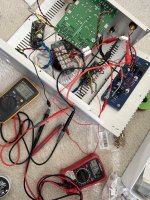
Ok now I have used a 0.1R/5w resistor in series with the positive supply and set the voltage across the resistor to 100mV to get 1A bias. Very stable and after that @Vunce I see power supply dropped to 16.4vdc with one channel from 17.5vdc.
Attachments
- Home
- Amplifiers
- Solid State
- Building an ultimate low power class A amplifier – my way