Miro, provide both, headers and ufls.
It would be nice if someone compare W8804 / DIR9001 / PCM2706 with modest clocks against newer, more expensive XMOS / CM6601 implementations.
DS DACs need this more complex digital front end, do R2R are effected by this and if so how much?
A module approach could help with these kind of tests.
It would be nice if someone compare W8804 / DIR9001 / PCM2706 with modest clocks against newer, more expensive XMOS / CM6601 implementations.
DS DACs need this more complex digital front end, do R2R are effected by this and if so how much?
A module approach could help with these kind of tests.
affected enough to sound bad : i.e. Damn DAC with clock and FIFO that has/had a terrible front end wasting the sound despite the R2R and buffer was good !
Front-ends are of a Great importance with PCM chips still (even if less sensible than DS but sensible enough to make it bad)
Front-ends are of a Great importance with PCM chips still (even if less sensible than DS but sensible enough to make it bad)
Pedja used PCM2706 quite some time before passing to XMOS. The reason behind this move IIRC wasn't the bad performance of PCM part but the technologies the new circuit introduced.
A proper A/B test is always revealing. As I stated, is not it wouldn't make any difference but how much.
A proper A/B test is always revealing. As I stated, is not it wouldn't make any difference but how much.
I've never got the need for usb myself as I pretty much solely use optical ( Google Chromecast) or rpi i2s. (Ians fifo next). I couldn't get on with wired source (mobile phone) to usb. In any case when I did try Amazom HD from Amdroid to USB it wasn't worth the hassle.
Maybe I missed something?!
Maybe I missed something?!
Diyiggy what is the correct value for the r10 output resistor???Congrats Miro for this next episode season 2 of the GoT DAC
The little DC traffo spliter sucks a lot of information. I know it's in all on the datasheet, but if one has a RCA with a dc blocking cap, it worths to try to remove it : the sounding difference is huge according the experience I made on an old AD1865 DAC. Also true AESBU with a simple coax TV cable all at the right impedance sounds much better than a RCA, but it means the streaming device to have one with the according circuitry (lesson learned from Jean-Paul and his fellow cool little ESS 9023 DAC which is sounding very correct for a Sigma Delta)
For R7 to R10, resistor choice is critical and not always mandatory, here again if no bouncing, a transparency sucker. I would avoid all not goo enough resistor here as the too much often seen in this thread Dale RN50 (the little brown one) : prefer through hole Yageo 1% precison : much better noise floor ; if SMD that are easy enough to solder : thin film from SUSSUMU has passed subjective listening test here as measurements : it's also easier to remove for zeo ohms than a THT with vias than are not easy here for tweaking (though boards are cheap at the famous JPLCB, and take not golded traces : it 's sound better")
You rocks Miro !
I m asking because here is 150r but i have seen 47k after opamp stages in other dacs..
So I've had mixed results with some of these cards. There are a few different varieties out there, some with CPLD, some have 3 clocks, some only 2. On one of mine I had to reflow the solder on one of the chips. On another, the 2 clocks were soldered in the wrong way around - I copped it when I listened and a particular track sounded off. Took me a while to realise that it was playing fast!! Once I swapped the clocks around it was fine. That prompted a chuckle.
Can't say I've compared the sound of them...
Diyiggy what is the correct value for the r10 output resistor???
I m asking because here is 150r but i have seen 47k after opamp stages in other dacs..
can you put a copy here or a link towards the shematic, I haven't under my eyes ! If you talk of the last buffer stage and its last serie resistor before the rca or dc caps : anytrhing between 120 to 150 ohms is correct, try 1/8 Allen Bradley trough hole or Suusumu if smd. I think if you saw a 47 K it was a shunt towards the Gnd.
Last edited:
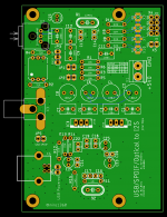
Ok guys, here are the uf.l connectors together with the pin header
Again untested = prepare yourself to be disappointed from a bug
Hip Hip Hurra.... I can't beleive it, I 'me just coming back from the church where I ligthed a dozen of candles for this miracle
Jim will use the output of his FIFO PI with good 2" uf l wires to keep the impedance and grounding correct ! The ones whom don't care leave the uf l traces unpopulated, cool !
Last edited:
I don t know were it is but r10 is the last resistor that is in series with the output of the last opa861 buffer. I had a dac in the past that had 47k in series with rca after the buffer opamp... never understand why and the reason of this resistors on signal path...can you put a copy here or a link towards the shematic, I haven't under my eyes !
I m listening with 150r sussumo.anytrhing between 120 to 150 ohms is correct, try 1/8 Allen Bradley trough hole or Sussumu thin film if smd. I think if you saw a 47 K it was a shunt towards the Gnd with a dc blocking cap before as a RC filter as well
The dac was an ak4495 and 47k in series not shunt to ground... on the last opamp before rcas..
Pan FC, sometimes FM in small values (both gives a different result, the Fm is the less good imho and sometimes have a fatiguing mid-treble, sort of smoothed harshness, depends on how it is used as well)
Panasonic FC is everywhere good. Very good quality, no extremely low ESR. Especially also in the restoration of vintage stuff (old Marantz...). But I think meanwhile FR (lifetime) ist the replacer of FM.
Hip Hip Hurra.... I can't beleive it, I 'me just coming back from the church where I ligthed a dozen of candles for this miracle
Never lose hope

Attachments
[emoji106][emoji106][emoji106][emoji846][emoji846][emoji846][emoji846]Never lose hope
@Vunce
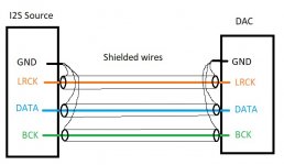
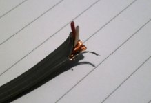
Use either a shorter 3x2 ribbon flat cable (IDC), or a twisted pair (signal+gnd for each signal: LRCK+GND, BCK+GND, DATA+GND) ... Don't leave those signal cables on the single GND
If you have only 4pin header with single GND, use shielded wires
Use either a shorter 3x2 ribbon flat cable (IDC), or a twisted pair (signal+gnd for each signal: LRCK+GND, BCK+GND, DATA+GND) ... Don't leave those signal cables on the single GND
If you have only 4pin header with single GND, use shielded wires
Attachments
Last edited:
...If possible, another request please....
Squeeze in a GND pad inline with the I2S header so a single row, 4 pos Molex connector can carry all I2S signal with GND.

@savvas
shielded ribbon cable is perfect
Attachments
- Home
- Source & Line
- Digital Line Level
- DAC AD1862: Almost THT, I2S input, NOS, R-2R