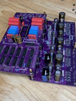
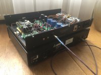
Are you guys ready for my discrete R-2R DAC?
It is working quite good, no audible glitches, but needs a while for deeper testing

 omg.
omg.I see quite a number of implementations using polyester caps, such as CDE orange drops and being favored by some. I guess polyester caps is not inferior in those positions.So pulling parts from my stash, I have a combo platter of TH PP film capacitors to use in these values:
0.1uF C40-42
0.3uF C43, 44
1.0uF C45
2.2uF C46
C15 (Cosc) = FKP2 680pF
The only 220nF caps in my stock are MKS (polyester)
@abraxalito For now it is powered by a simple MC7805 regulator There is definitely less digital noise than on any discrete R-2R I've tried so far (and it has no filter).
First I need try to decrease voltage for digital part by a 0.5V and see if there are some improvements
There is definitely less digital noise than on any discrete R-2R I've tried so far (and it has no filter).First I need try to decrease voltage for digital part by a 0.5V and see if there are some improvements
7805 is about 100uV noise? I take it by 'for now' that you'll be looking at upgrades....
'Digital noise' - you mean on the digital supply? Or 'digital' sound at the output?
Output noise in datasheet is 10 uV/VO (load regulation is 0.5mV). Sure, i will test this
I do few small corections on the PCB and post everything here.Not sure if that was digital noise. It was caused when LE (latch) clock was active. It was probably digital because it was quite distracting. On my DAC is is quite - more like a very low white noise, not bad
I found it!Exactly aj @Brijac told, most probably it is somewhere near a solder joint. (if you check the PCB, GND plane is very close to each solder joint)
... if not, than remove J9 jumper and measure ...
The C6 legs were connected as a result of my soldering. 🤦♂️
I hope I didn’t burn the ad11862 chips 🤞
Looking forward to get burnt fuse replacement.
Thank you guys for your help!
I can stress enough though, of using proper soldering gear for sensitive and components. Everything matters, solder, soldering station and proper tips, use of quality flux to reflow joints. This way you at the very least avoid solder whiskers that will short circuit your components.
Yep - just leave out the capacitor for non-AIs plain TD1541 compatible? I see it is just the 2 oscillator pins that are NC on non A.
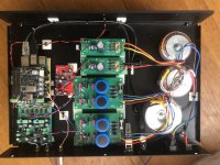
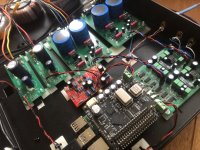
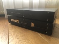
Another AD1862 build. I don't use "hifi" parts but just high quality brands/components i had lying around. I have a Sonneteer Byron CD player whitch i wanted to use as a transport. I used an old molested Sonneteer phono chassis and anodized the faceplate again, new laser fonts, new rearplate and fresh powdercoating.
Attachments
Last edited:
Looks promising Vunce…And the journey begins!
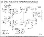
😉Protection against DC offset voltage on DAC or Preamp output
It is definitely not needed for DACs like AD1862, AD1865, maybe PCM63? Because they have zero DC offset even if the signal source is not turned on.
TDA1541A is another animal and when the signal source is turned off, then a DC offset appears on the output. It has some internal biasing and most manufacturers used audio capacitor in the signal line to prevent this DC offset on the output. I am not a fan of coupling capacitor because it colors the sound I assume you won't use it either, so the correct power-on sequence for the TDA1541A is: first turn-on the source and then turn on DAC TDA1541A).
If the input signal were to be disconnected for some reason, an DC offset would appear at the output due to the missing output capacitor. So it would be good to consider one of two options: Either install a high quality audio capacitor on TDA1541A DAC output, or use this DC protection on the output like I did.
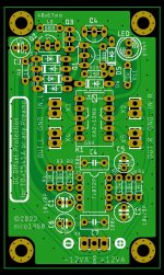
This DC protection is small, cheap and very simple. When the protection is kicked in, the LED indication is off (the relay is disconnected).
IN_L + GND and IN_R + GND connect with DAC outputs.
OUT_L + GND and OUT_R + GND are now the protected outputs.
Power up it from +-12VA directly from DAC. If you power-up it with higher voltage (max. +-15V) then change R10 to 330R.
Reset time is set by R9+C3 = how long will be the protection off after DC voltage disappearance. If a faster reset is needed then lower the capacitor value.
Reaction time is set by R1+C1 and R4+C2 = how fast it reacts on DC offset presence. If a faster reaction is needed then lower the capacitor value.
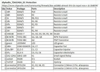
BOM example:
https://www.mouser.com/ProjectManager/ProjectDetail.aspx?AccessID=b9874b7786
(the small relay is again not stocked, use this alternative: 551-EA2-12NJ)
It is definitely not needed for DACs like AD1862, AD1865, maybe PCM63? Because they have zero DC offset even if the signal source is not turned on.
TDA1541A is another animal and when the signal source is turned off, then a DC offset appears on the output. It has some internal biasing and most manufacturers used audio capacitor in the signal line to prevent this DC offset on the output. I am not a fan of coupling capacitor because it colors the sound
I assume you won't use it either, so the correct power-on sequence for the TDA1541A is: first turn-on the source and then turn on DAC TDA1541A).If the input signal were to be disconnected for some reason, an DC offset would appear at the output due to the missing output capacitor. So it would be good to consider one of two options: Either install a high quality audio capacitor on TDA1541A DAC output, or use this DC protection on the output like I did.
This DC protection is small, cheap and very simple. When the protection is kicked in, the LED indication is off (the relay is disconnected).
IN_L + GND and IN_R + GND connect with DAC outputs.
OUT_L + GND and OUT_R + GND are now the protected outputs.
Power up it from +-12VA directly from DAC. If you power-up it with higher voltage (max. +-15V) then change R10 to 330R.
Reset time is set by R9+C3 = how long will be the protection off after DC voltage disappearance. If a faster reset is needed then lower the capacitor value.
Reaction time is set by R1+C1 and R4+C2 = how fast it reacts on DC offset presence. If a faster reaction is needed then lower the capacitor value.
BOM example:
https://www.mouser.com/ProjectManager/ProjectDetail.aspx?AccessID=b9874b7786
(the small relay is again not stocked, use this alternative: 551-EA2-12NJ)
Attachments
Thanks Miro, yes it works perfect.
There are many DC protection circuit out there that will serve the same purpose.
This is only one of them for line level, with adjustable trigger voltage, power-on delay, and optional error latch :
https://www.diyaudio.com/community/threads/xen-shpp-simple-headphone-protection.292681/
In a later (2020) edition, we went for a bi-directional optocoupler instead of BJT trigger circuit, further simplifying.
Cheers,
Patrick
Are you guys ready for my discrete R-2R DAC?
Over the years I have seen many designs of Discrete R2R DACs, with claims that they sound better.
I have seen next to no performance measurements though.
The fundamental design of a discrete R2R DAC is well explained here :
http://www.sonicillusions.co.uk/discrete_dac.htm
And most of the problems of such designs are well known, including the need to use 0.01% resistors, etc. :
https://www.diyaudio.com/community/...-magnitude-24-bit-384-khz.259488/post-3999275
https://www.diyaudio.com/community/...-magnitude-24-bit-384-khz.259488/post-4004298
https://www.diyaudio.com/community/...-magnitude-24-bit-384-khz.259488/post-4010487
So I very much look forward to you showing us something original and innovative, whenever you are ready to do so.
Cheers,
Patrick
- Home
- Source & Line
- Digital Line Level
- DAC AD1862: Almost THT, I2S input, NOS, R-2R