I spent extended time listening to the Sparkos SS3601 in the miro AD1862 DAC that I built and tried to compare it to the sound of the Burnson V6 vivid that I wrote about in post #5449. In short, they sound similar to each other. There are some small differences, but it is difficult to say which one is better, even swapping them back and forth several times. I would have to say that they both sound very good and I would be happy with either one, which is what NIXIE62 said in the post following mine. That being said...I found myself eventually gravitating toward leaving the SS3601 opamps in the DAC. I cannot exactly explain what each sounds like (No, I am not going to talk about the "decay of a guitar pluck" or "air around the piano"), but I can say I do not feel like trying any more opamps right now. I think I will sit back and enjoy my music collection again for awhile. If someone else feels like it, they could try some different values of feedback capacitors, which may squeeze out a slightly better sound. After all, the DAC output is a combination of many tiny square waves, but both opamps seemed to handle it well with the filtering that I mentioned in my previous posts. My system is what I call very revealing. It is not leaning toward bright or toward warm. You may prefer something else in your system.

The sound of each OPA can be changed for the better (at least in my opinion) by adding a mosfet source follower included with NFB to its output. In this way, you get, for example, a preamp that works in A class and SE up to some 2V RMS or little more. I have made mini preamps with and without mosfet, and the one with mosfet sounds better. I think it could be applied here as well in the active I/V assembly.
Attachments
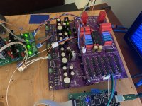
I fired up the TDA1541A DAC today and was greeted with distorted music  .
.
Before the 1541 chip and opamps were installed all voltages were confirmed to be correct.
Then 1541 was installed and a signal fed to it, zero'd the offset without opamps in sockets.
Installed opamps and connected DAC to audio system. Distorted sound is the result.
The power supplies and USB interface are confirmed to work properly in previous Dac builds.
I verified the shift registers are in their proper locations. This one has me stumped.
.Before the 1541 chip and opamps were installed all voltages were confirmed to be correct.
Then 1541 was installed and a signal fed to it, zero'd the offset without opamps in sockets.
Installed opamps and connected DAC to audio system. Distorted sound is the result.
The power supplies and USB interface are confirmed to work properly in previous Dac builds.
I verified the shift registers are in their proper locations. This one has me stumped.
Attachments
@NIXIE62
Yes, but you can also find an opamp with emitter degeneration resistors (which introduce NFB). I'll be producing a batch in January, with and without e.d. resistors and see which one sounds better. One thing about them is that by reducing open loop gain, it linearizes the transfer curve. The larger it is, the more it lowers o.l. gain, and more linear it is. So there must be a balance.
Yes, but you can also find an opamp with emitter degeneration resistors (which introduce NFB). I'll be producing a batch in January, with and without e.d. resistors and see which one sounds better. One thing about them is that by reducing open loop gain, it linearizes the transfer curve. The larger it is, the more it lowers o.l. gain, and more linear it is. So there must be a balance.
These Sparkos - are they much better than LM6171? You just swapped them or needs of the some modification for the Dac board?I spent extended time listening to the Sparkos SS3601 in the miro AD1862 DAC that I built and tried to compare it to the sound of the Burnson V6 vivid that I wrote about in post #5449. In short, they sound similar to each other. There are some small differences
@Vunce
Hope that yours TDA1541A is not damaged
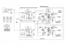
... is C15 capacitor installed?
1. Check if I2S pins are not swapped and have good contact and if I2S device is configured properly
2. Measure with multimeter for unwanted short all neighboring pins from the top of each logic part.
3. Measure these pins for possible short with GND
I am sure we will find the solution 😉
Hope that yours TDA1541A is not damaged
... is C15 capacitor installed?
1. Check if I2S pins are not swapped and have good contact and if I2S device is configured properly
2. Measure with multimeter for unwanted short all neighboring pins from the top of each logic part.
3. Measure these pins for possible short with GND
I am sure we will find the solution 😉
I tried to leave a link to my previous post where I mentioned that I mounted the components underneath the board that are near the DIP8 sockets to make room for potentially large opamps, like Vunce showed us (see post #1 for reference). I also mentioned the opamps that I have listened to, which does not include the LM6171. So, I do not know, but I think the SS3601's will sound better...maybe worth a try. I am happy with them, as others have said.These Sparkos - are they much better than LM6171? You just swapped them or needs of the some modification for the Dac board?
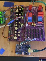
Pulled the DAC board and did another visual inspection, no shorts or solder bridges. I decided to swap out the Singxer C1 USB to I2S converter for JLS I2SoverUSB board configured as in post#617.@Vunce
Hope that yours TDA1541A is not damaged
... is C15 capacitor installed?
1. Check if I2S pins are not swapped and have good contact and if I2S device is configured properly
2. Measure with multimeter for unwanted short all neighboring pins from the top of each logic part.
3. Measure these pins for possible short with GND
I am sure we will find the solution 😉
Bam-O Wham-O!!
TDA1541A MiroDac is Singing 🥳
The Singxer C1 plays well with all my other AD1865 and AD1862 DAC’s but is not friends with TDA1541A, probably a bit/sample frequency issue.
Thank you for sharing another successful creation Miro!!

Attachments
@NIXIE62
Yes, but you can also find an opamp with emitter degeneration resistors (which introduce NFB). I'll be producing a batch in January, with and without e.d. resistors and see which one sounds better. One thing about them is that by reducing open loop gain, it linearizes the transfer curve. The larger it is, the more it lowers o.l. gain, and more linear it is. So there must be a balance.
That's another story entirely. I experimented with mosfet source follower when I had factory OPA, NE5532, LME49720, OPA2604, OPA1612, OPA1622 and similar. I found this schematic on the Internet and decided to try it. And it definitely sounds better than OPA in AB class, and the DC offset is minimal so there is no output coupling capacitor.
Ahh, you thought OPA IC opamps. I confused it with discrete, knowing most of those work in class A and have emitter degeneration resistors.That's another story entirely. I experimented with mosfet source follower when I had factory OPA, NE5532, LME49720, OPA2604, OPA1612, OPA1622 and similar. I found this schematic on the Internet and decided to try it. And it definitely sounds better than OPA in AB class, and the DC offset is minimal so there is no output coupling capacitor.
Sparkos & Burson came later. Even with them there is a slight difference in favor of the mosfet source follower, but not as much as with the factory OPAs operating in AB class. Since the gate resistance is huge, even factory OPAs never leave A class, except perhaps at very high frequencies where the charging current of the input capacitance of the mosfet transistor comes into play. But it's somewhere far away, it's not of our interest in the audio range.
I use 4.7/47uf tantalum noise reduction capacitors on my ad1862 dacs (not Miro's). Don't know if tantalum makes any difference to electrolytics.Miro, can i ask why you choice 4.7 and 47uf electrolitics for C15,C25,C16 and C26? And not 1uf (or2.2) and 10uf(or22) tants?
Can there be experimented with these?
@Vunce, nice work! just curious, for C1-13 (0.1uf bypasses for the logic chips) are you using smd mlcc caps? can't really see clearly in your pic.Pulled the DAC board and did another visual inspection, no shorts or solder bridges. I decided to swap out the Singxer C1 USB to I2S converter for JLS I2SoverUSB board configured as in post#617.
Bam-O Wham-O!!
TDA1541A MiroDac is Singing 🥳
The Singxer C1 plays well with all my other AD1865 and AD1862 DAC’s but is not friends with TDA1541A, probably a bit/sample frequency issue.
Thank you for sharing another successful creation Miro!!
the tants should have lower esr and better hf filtering. The specsheet mentions 1 and 10uf or 2.2 and 22uf. I think Miro uses higher value uf because higher value electrolitics has lower ers and are cheaper. I was curious of this was the reason of his choises for electrolitics?I use 4.7/47uf tantalum noise reduction capacitors on my ad1862 dacs (not Miro's). Don't know if tantalum makes any difference to electrolytics.
Larger noise reduction caps may lower noise according to datasheet.the tants should have lower esr and better hf filtering. The specsheet mentions 1 and 10uf or 2.2 and 22uf. I
My AD1862 (N-J) dacs have about as low noise as datasheet predicts (-98dB THD+N). Without MSB trimming it is quite impossible to reach datasheet levels.
- Home
- Source & Line
- Digital Line Level
- DAC AD1862: Almost THT, I2S input, NOS, R-2R