until we see your 4-layer DAC, there is no point arguing with you, a lot of talk and no actionThe listening checking is always made at the end in a particular system. Here yours. At least if you listened to it. No matter what is saying the measurement and scopes that are good in many DACS. I think such a phrase has no sense, but marketing or self awards. Not a judgment. I am sure it sounds good but has drawbacks, first because the choice as an I/V W Jung himself alerted (better it is for a buffer) then because it is never something that has an no-end. I.e., you never know untill you found or heard better. I do not say to people not to try it, they should, Vunce told me he really like it in his system. And it is okay. Others than me told you already they do not think current opamp are the best choice in opamp categories for that I/V task. Hey I do not say it is bad and you will not hear me judging on sound description that has no sense because it is the room, the biased people, the rest of the system, etc. We are experienced enough to weigth the poors and cons when someone testimonies with his system full description (and even so we do not know, we are not in the room, etc)
And I never know a guy who can judge from a scope and measurements but to avoid the best worse designs I am sure your are not. (cause at least it passed the test of another guy here)
And I think we all want a realistic image, etc. Mine has, your has, it is okay ! And do not play with the words, if you made it it pass your ears checking whatever it is for you or others. And so it pass in a known environment. If it is good here it can be good somewhere else... or maybe not. But having as many, several systems, each DAC, whatever being high level sounding have better marriage in a system than another. That's all I wanted to highligth behind the superlatives many like to congrat themselves and that eventually bias others untill they hear better . Simple two cents sociology and logic.
Have you seen superlatives from me when I described my design few pages ago (here just the layout, as I have the modesty no to comment on my personnal choices on the OPASs).), not really. It was a good enough, whatever I find it is really good...in my system. I want it to be clear (the meaning). I know two things too about the sense of the words Grunf and my ears are surely as old and experienced as yours
But all is okay, I just have an average seldom about readings too and always think I can help to decipher for less experienced than us. Also not everyone can test them all, so prudence is a good friend as well.
cheers
very french cubisme words than "Ceci est un cube" (amplifier). https://forums.melaudia.net/showthread.php?tid=7260
In an era where chinese ess dacs are all over the place, and sound literally the same up to 1k, even more $, cheaply made nos r2r dac eat them aliveThat "many, many times" sweet spot is imho, more often than not, pure fantasy, but it's the trip that matters, not the destination, right?
If i were you i would absolutely add a reclocker to that usb board. Good clocks made a good improvement upon the Mk2 board, but are an absolute must for the Mk3, where reclocking after the galvanic barrier is done not in physical flip flops but in FPGA.
Not to mention you can make these dacs as high end as possible (budget allows).@grunf they are made in smd. Everything i make is smd
And this picture is of burson v7v test. I run a custom output stage.I would be more than happy to Gerber one of those Walt Jung regs.if you have an electronic schematic, this would help. Everything under your supervision, of course.until we see your 4-layer DAC, there is no point arguing with you, a lot of talk and no action
If it's not too much for Miro's DACs!
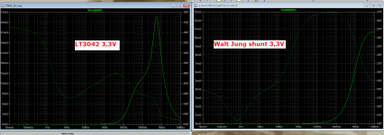
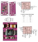
Grunf, I am sorry to say but your simulation of that LT3042 circuit is terribly off. I can imagine many causes that you are doing wrong. I can simulate close to what I can measure, instead.
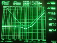
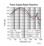
So let's confront your simulated LT3042 impedance curve against my !measured, real life impedance curve of my LT3042 regulator. The impedance at the lowest point (bottom of the curve at ~100kHz is at 7mohm, and it is still <10mohm at 1MHz and a bit above)
The upper, fade out trace is the output 10uF MLCC capacitor impedance alone.
It needs a minimum care to bring out datasheet performance, (and even more to be able to measure it)
Attachments
And than not to forget PCB track resistance, which easily adds in the 0,0X Ohms.
Therefore sense connections up to mm's from the load help.
I'm using 9 Jung-Didden superreg's with sense connections: everywhere I have a flat line on my scope, even the digital power pin's right at the AD1862. Had a review last week with a person who has a lot of listening experience on a lot of systems, he was really imressed when I compared back and fort with my (now in unuse) Bluesound DAC.
https://www.diyaudio.com/community/threads/dac-gallery.166807/page-23#post-7679581
Again a personal attack....pffffff, try first what I posted few post ago : gerbers and free design too, choose your own multiple conf and judge it for free then come back as you have things to say ! And what I argued has not to see with the numbers of layers, don't fall in false elements of language like my poor countryfellow dude elswhere. There is no reasonments in what you say but sliding from a tech conversation to personnal accusations. If I'd go this path I 'd ask you where are your 4 layers and how about smd with your tht pcbs 2 layers (that is ok when not more is needed) But I do not .until we see your 4-layer DAC, there is no point arguing with you, a lot of talk and no action
And common ? "no action" : I give a tons of tips to try here and elswhere in that thread and forum, done many things that profit diyers more than you did, and just gave a two layers gerbers few post ago to makes some tries. Your direct attack is so delirious than you even can not understand about dialectic when people ask a question for the help of the readers (is dialogic word is known to you?).
So fed up with people that have no arguments and are in the accusations all the time as you do with me (and again as my countryfellow your congrats each others when it comes to attack me with fake arguments like: I do not share, etc). So you are using the same dishonest practice with that made an another dude with you support each others. When you run out of argument you slide in the accusations about a said work that would be better than what other did. Very unfair and dishonest, very bad dialectic too ! I given many things in this thread before you put you feet here. And suffer people have opinions too.
That's okay, I just defend about your unfair attacks that are personals like my countryfellow did because no more arguments to answer vs what I highligth !
Again I shown you already and many followed me that what you said on EI ecc88 was false and there is a thread about it. So It is ok for me, just I have the rigth to say you are wrong sometimes technically when it is true you are. And I do not understand your reaction as I do not say, far from this, your work is bad !
About my 4 layers, due to what you posted untill now, I am not sure you will understand half of what I made (EMI/EMC, digital routing and groundings, etc) , but it is okay as it is not shared; and I said already the two OPAs conf on 2 layers I posted on half the base of miro1360 could be a progress according one's needs. And a good tool to go further.
Is it about dialectic about you just because I highligth technicals things I disagree because of the superlative words that come with them ? Ego things ?
You will figth alone then, I only discuss what I see and, oh, I am not the only one about what you say just see feww posts before. And again I said all is not bad. So calm down, mate, please. I am very not impressed, and sorry for that but you begun first what seems AGAIN (and certainly with an agenda) sliding from technical to personal attack because you have problems about technica&l critisms.
Is it clearer, are we ok, if I say nothing personal and can I ask you the same ? Was I wrong when the W JUNG paper said AD811 was not for I/V but better for buffer ? Do you attack me on personals to make a smoke screen ? It is okay with me guy, just I am not a young bird and as stupid you think I am, hey
I hope because dialectic is important, people that are less skilled than you and me will sort out by the question and answers dialogs what is good and not with the support I made to try it, yours stuffs also. So what ? And jump to something else than your pcm1702 or TD11541A (oh it is ok I work on it from 25 years too
)... try AD1962
Last edited:
On an experimental point of view, IMHE, I didn't like LT30xx family too, have a poor experience with it on digital clocks, testimonied long time ago here about that on oldest IanCanadas clock boards.
I prefer the expensive AD7x or TS7A families. I am not sure discrete to be always better. Layout is important too as passive parts, when you have sorted out the minimum needs (impedance, noise and so on). There are also alas always sonic dependancies when you check with listenings according the rest of the system... Something than makes us all humble at the end as it is not easy to rule or there will not be forum for that.
I prefer the expensive AD7x or TS7A families. I am not sure discrete to be always better. Layout is important too as passive parts, when you have sorted out the minimum needs (impedance, noise and so on). There are also alas always sonic dependancies when you check with listenings according the rest of the system... Something than makes us all humble at the end
as it is not easy to rule or there will not be forum for that.Unfortunately, I get the same thing if I use the original LT LT3042_DC2246A asc file, so I think there really is some problem with the simulation, not my fault.Grunf, I am sorry to say but your simulation of that LT3042 circuit is terribly off. I can imagine many causes that you are doing wrong. I can simulate close to what I can measure, instead.
So let's confront your simulated LT3042 impedance curve against my !measured, real life impedance curve of my LT3042 regulator. The impedance at the lowest point (bottom of the curve at ~100kHz is at 7mohm, and it is still <10mohm at 1MHz and a bit above)
The upper, fade out trace is the output 10uF MLCC capacitor impedance alone.
It needs a minimum care to bring out datasheet performance, (and even more to be able to measure it)
It was suspicious to me too and I get a similar result with ADM7151 in LTspice.
I know that the LT3042 and ADM7150 which I used in my DAC before are excellent regulators but for digital they are better shunt regs regardless of their greater dissipation and complexity. Whether it makes sense to complicate the design so much with shunts is another story.
I think it would be a good exercise to rectify this discrepancy, for better 'public' understanding here..
May I ask at what load current do you execute this simulation?
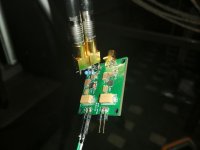
On the photo of mine, You can observe a parallel load resistance. My measurement had been done at 50mA standing current. You must establish a minimum standing current for these regulators, to perform as designed.
In my experience, if you neglect this than You get the peaking that you show..
May I ask at what load current do you execute this simulation?
On the photo of mine, You can observe a parallel load resistance. My measurement had been done at 50mA standing current. You must establish a minimum standing current for these regulators, to perform as designed.
In my experience, if you neglect this than You get the peaking that you show..
Not my experience. Simulations or datasheet do not point to that either. In simulations there is a slight bump in output impedance at about 1MHz regardless of load although not necessarily as high bump as in grunf's simulation.You must establish a minimum standing current for these regulators, to perform as designed.
Here is another measurement of output impedance.
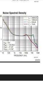
all the datasheet curves had been taken at 200mA /500mA load current. (and no output impedance measurement)
The Cocolog guy is fantastic, I had followed his blog closely.
In my measurement i could not be so precise, the floor flattens out much higher than the micro-ohm levels he releived.
There is a hint in the datasheet about the useful bandwith vs load current, and it shows that 1MHz is only reached at >50mA load current & above:
Attachments
I didn't like LT30xx family too, have a poor experience with it on digital clocks, testimonied long time ago here about that on oldest IanCanadas clock boards.
Must have missed this. At the time of the 3042 fever i felt i was the only one thinking they sounded very unimpressive in clocks.
I must be difficult with sounds (I believe it is due to my loudspeakers that have mid and tweet in aluminium) I didn't like the LiPo cells too and gave up that way too. Was with the Crysteq CH957 something if I remember. That Crysteq improved a lot with a local decoupling of 1uF acrylic cap on Ian's board. Then Ian used a Rubycon of the same material family on his Fifo Pi but with a higher capacitance. Mine was The Cornel Dublier FCA, I still use in my dac boards or others'.
Now things improved till Andrea Mori's work on clocks !
Now things improved till Andrea Mori's work on clocks !
Last edited:
Do You remember what reference filter value (the bypass cap on the voltage setting resistor) had been used? What type? That has quite an influence on the low frequency noise of the regulator.Must have missed this. At the time of the 3042 fever i felt i was the only one thinking they sounded very unimpressive in clocks.
I hope the datasheet suggested ~10uF output capacitor had been applied.
Then again: Clocks typically present too low current load. Parallel extra resistor could be needed, should be calculated.
I am not against alternative solutions, but they should perform better in a proven, measured way. That is quite a barrier in case of the LT30** family.
Look at PSRR vs. current. It tells exactly the opposite. I don't see how lower noise density (i.e. better) at 1mA indicates anything about bandwidth.all the datasheet curves had been taken at 200mA /500mA load current. (and no output impedance measurement
...
There is a hint in the datasheet about the useful bandwith vs load current, and it shows that 1MHz is only reached at >50mA load current & above:
Attachments
Yes, sure. With all those internal ceramic capacitors external acrylic cap will surely make a huge differenceThat Crysteq improved a lot with a local decoupling of 1uF acrylic cap on Ian's board.
https://www.diyaudio.com/community/threads/inside-a-cchd-925-output-dead.396310/post-7280163
Do You remember what reference filter value (the bypass cap on the voltage setting resistor) had been used? What type? That has quite an influence on the low frequency noise of the regulator.
I hope the datasheet suggested ~10uF output capacitor had been applied.
Then again: Clocks typically present too low current load. Parallel extra resistor could be needed, should be calculated.
I am not against alternative solutions, but they should perform better in a proven, measured way. That is quite a barrier in case of the LT30** family.
I used ready made modules and after disliking the clear, thin, lacking in texture sound, ended up replacing the filter caps with Panasonic ECP and the outputs with OScons. No obvious change, certainly not for the better; the strong, inherent to this part sound signature remained. And, yes, did apply an additional load.
Attachments
Yes I know. But obviously it makes one. Seems not to be autobias as @Markw4 did apply that tip and you can see that acrylics cap that are class 1 equivalent (see FCA datasheet) that pop ups evertwhere, also in commercial brands.At least it works fine with this Crystq. Maybe it just needs a bigger local decoupling low inductance at the feets and the class 2 makes toi much noise for a crystal, dunno.Yes, sure. With all those internal ceramic capacitors external acrylic cap will surely make a huge difference
https://www.diyaudio.com/community/threads/inside-a-cchd-925-output-dead.396310/post-7280163
Where is the logic, I do not know always. Like some use MELF resistor that have higher inductance than smd thin films in their circuitry... or some others carbon comp or carbon and after checking it sounds better when mixed with metalfilms, it is surely we do not measure the good things perhaps...but I do not know. Some others use UKZ in decoupling all the time, I do find they have too much short bass low end often... everyonne seems to have their own... hummm logic.
Yourself has shown you hear almost the same between 4 i/v conf in your experiment (thanks for that litle good thread).... maybe we cut the fur in four. You said also you didn t liked the opa861 it sounded terrible for your ears. Quite the opposite for me. My best dac which is from Audial Rogic TDA1541A dac with iancanada front ends and some tweaks are eating all the others I had or do since. Musician friends agree. So....
Edit: is your MarcelvdG iteration pcb public ? You make very good job i find with smd layouts. It has obviously some advantes to proceed like that
Last edited:
With uncontrolled subjective listening tests any outcome is possible regardless of number of listeners. Anything related to sound reproduction before the sound enters your ear is measurable. What happens in your head is not measurable so even if seems obvious to you it very likely is not to everyone. So this is about opinions and yours is not better than e.g. mine.But obviously it makes one.
- Home
- Source & Line
- Digital Line Level
- DAC AD1862: Almost THT, I2S input, NOS, R-2R