These are the caps I have. I’ve accumulated quite a few - if you’d like a couple freebies, shoot me a pm. TO-5 Thermal Cap for TO-92 Transistor Pair FET BJT (2SK170 etc) - bag of 30 pcs | eBay
... the quick disconnects terminal blocks to fit in the front end boards. Note, the terminal blocks are not in the kit. They’re from my stash.
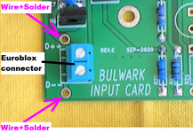
The other four front end boards have PCB component footprints for both soldered wire connection and Euroblox screw cage connectors, so builders can use whichever of the two possibilities they prefer. Euroblox part numbers are listed in the Detailed Parts Lists and they are part of the one click Mouser Shopping Cart. They fit beautifully without needing to bend the pins

You can see them in this photo; the Euroblox are sky blue plastic rectangles, located at approximately 11 o'clock , 3 o'clock , and 7 o'clock on each circuit board. Click on the photo to see it full size and undistorted:
_
Attachments
Last edited:
Wow, you guys are FAST! So many posts in the last day... great to see.
While I'm still waiting for chassis and some time to fire up the soldering iron, at least I've been able to noodle on some aspects of this build... and I remembered a special box that I had tucked away. I always knew I'd find a good use for these beauties (future upgrade, will build the stock kit first, then start work on a front end of my own design)... 290kHz and +27dBu's worth of quadfilar deliciousness. Roughly the same vintage as those Sony VFETs, too.
take care about ratio
if you use it as regular Xformer ( not autoformer) ...... originally used Edcor 600:15K is having a gain of 5V/V
Time to see how far I can get with mounting and wiring the PCBs today. I've scavanged some screws from my Ultimate 4U, 500mm deep chassis and will replace them with VFET chassis screws once those arrive.
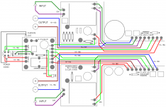
The color wiring diagram in Nelson's Sony VFET pt1 manual is the key:
The color wiring diagram in Nelson's Sony VFET pt1 manual is the key:
Attachments
And you have already gone through the burn in...
Hahahaha, I just spat my coffee all over my iPad!
It’s not OK to make fun of other’s miss happenings, but this one was priceless!
Hahahahaha, can’t stop laughing!
Sorry again Codyt!
Rafa.
Rhthatcher, I also had two extra 100R resistors.
Those "extra" 100 ohm resistors are R7, which goes from chassis ground to FE ground.
The color wiring diagram in Nelson's Sony VFET pt1 manual is the key:
For those who are not colorblind.
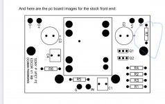
There is no footprint for R7 on the FE board.
Here’s the photo I’m referencing, from the documentation
Attachments
- Home
- Amplifiers
- Pass Labs
- DIY Sony VFET Builders thread