In the future I am going to throw away all older versions of boards...
Please, throw them in my bin! I will put them to good use!

Really... did you never saw people digging through the company's garbage? It must be a goldmine...

Another alert?
This is important to share if it is a general issue, I guess it is... You dont want to kill your Vfets because of thermal overheating!
The other incident I had with mine, is the four 3mm bolts retaining the output board to the heat sink bottomed out before the heat sink was tight to the output board. I used an extra two 3mm flat washers on each bolt to prevent the bolts from bottoming. I found it by gently moving the output board, I was surprised when it moved. I think the grease between the heat sink and output board helped me find the bottoming bolts.
This is important to share if it is a general issue, I guess it is... You dont want to kill your Vfets because of thermal overheating!
What's the difference between this 2021 Sony VFET amp the original 2017 Sony VFET amp?
2017 is pushpull
2021 is single ended
Hard to keep track of all the SIT threads going now....had to post so I get updates and don't loose this thread.... Ordering up the hard to get and long lead time items.
A big Thank You to the DIYaudio community!
You can go into "thread tools" and subscribe to threads you want to keep track but don't want to post. Then, in "user CP" you can go into "subscribed threads" to quickly see all the areas you are participating in. It's mostly the only way I consume threads here. Hope it helps.
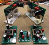
Installation of the FE and OS boards onto the heatsinks is not something that can be rushed.
While the OS PCBs are identical, the aluminum mounting brackets that house the output transistors are not identical. The correct mounting position is the one that places the PCB closer to the front plate of the chassis. The correct mounting position also results in PCB orientation that agrees with the color wiring diagram.
The M3 mounting holes that are used for the OS brackets need to be cleaned up with a M3 bottom tap. This will make sure the screws are properly snug against the bracket. Alternately, one can file off a couple threads worth of the M3 screws, or add another washer or two, if available. Since I'm used to needing to clean up mounting holes, I have an M3 bottom tap available. One can convert a M3 plug tap into a bottom tap by grinding off the pointed end of the tap until it is nearly square. I like to do this on a bench grinder.
It is best to clean the mounting holes before applying the thermal grease. Yes, I did this backwards, and realized that the screws were bottoming out too early as they became tight before the heads were snug against the OS mounting bracket. The screws for the FE boards will be fine as there is a nylon spacer between the PCB and the heatsink.
There is only one way to orient the FE PCBs so that all four mounting holes line up with corresponding holes in the heatsink.
Attaching the baseplate onto first one, then both heatsinks will establish the distances between the channel boards and the small power filter board. There is one correct way to attach the base plate (and top plate). This is with a small overlap to the rear of the chassis, not the front. The big front plate covers the entire front of the chassis, so the heatsinks, base plate and top plate all need to be flush with one another for the front plate to mount correctly.
Have fun!
Just reading thru all the posts while I wait for my parts to arrive I'm curious regarding the RB7 power plug on the Meanwell.I was looking at the online info and it says the -ve terminals are attached to the AC FG which stands for AC Frame Ground which i'm assuming is the metal outer barrel of the plug.I don't know what the chassis receptacle for this plug is like but does it have a metal sleeve that attaches to the mounting screws of the receptacle? Reason I ask because if that's the case then the thermistor would be shorted out. A quick ohmeter check between the -ve terminal(s) and the chassis with the Meanwell plugged in would verify this.I just found this on the Meanwell info sheet "A type: Class I (with FG), IEC320-C14;" which is the 160W model we have,so it looks at face value that plug has the FG barrel attached to the -ve pins.
Looks like a red herring,on further investigation it looks like the shielded receptacles have a metal plate and the non shielded ones are black plastic which from the pictures here are the ones we have.Sorry for the rant,its what happens when you're retired and locked down.
Follow the color wiring diagram. The DC power conn has six pins, and two of those are connected to the chassis and cable shield. The connection to the chassis is made on the small power filter PCB.Looks like a red herring,on further investigation it looks like the shielded receptacles have a metal plate and the non shielded ones are black plastic which from the pictures here are the ones we have.Sorry for the rant,its what happens when you're retired and locked down.
The guide is open, as there needs to be some information available for people jumping in with both feet. (Which is very cool...)
It’s not complete yet, I’m on he road for another couple days and should have it done reasonably well by 23 April.
All Guides - diyAudio Guides
It’s not complete yet, I’m on he road for another couple days and should have it done reasonably well by 23 April.
All Guides - diyAudio Guides
The guide is open, as there needs to be some information available for people jumping in with both feet. (Which is very cool...)
It’s not complete yet, I’m on he road for another couple days and should have it done reasonably well by 23 April.
All Guides - diyAudio Guides
@ 6L6
Thank you very much for new fabulous excellent SE Vfet guide
 Sony Vfet (P, 2021) - diyAudio Guides

The guide is open, as there needs to be some information available for people jumping in with both feet. (Which is very cool...)
It’s not complete yet, I’m on he road for another couple days and should have it done reasonably well by 23 April.
All Guides - diyAudio Guides
Thank you as always for the exceptional guides!
I will send all rejects to ZM for disposal.

I had/have no complaint having/using preproduction boards, I was just curious what method others used for mounting R7. I was expecting and hoping, this build to challenge me, Jason said to expect the unexpected.
I'm done for tonight, time to celebrate the day's work and the day.
I'm sure I can't be the only one with this question...
In the wiring diagram, it is showing the outer tabs of the power connector (continuity to -Vo and mains Earth) connected directly to the chassis.
Is this similar to the safety GND for a mains voltage supply? Chassis is connected directly to mains earth, and "Audio GND" or all the "G's" on the boards are lifted through the thermistor....?
Did some quick DMM readings, and that seems to be the case, but wanted to confirm.
I will send all rejects to ZM for disposal.
as long there are Greedy Boyz around, there are no rejects from Papaland


- Home
- Amplifiers
- Pass Labs
- DIY Sony VFET Builders thread