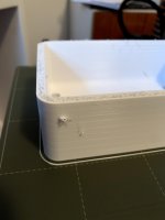
Here is the half printed in two parts. Now the quality is perfect, it just needs a bit of work with a knife. When I glue the two parts together (there are some holes to align, but it will need to align also at the fron), I will maybe sand and paint the horn start as it is the only visible part. The flange is connected with two M4 screws with a square nut and two self tapping screws - and also with the threaded rods which will hold the AMT inside. The for the AMT is slightly loose so some thin gasket needs to be put below the AMT. For a perfect fit the thin inner part could be heated and pressed to fit or again some thin flexible gasket put below. I will post the STLs later if anyone is interested.
Attachments
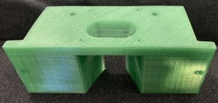
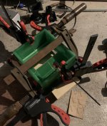
I use M4x10 screws with cut off heads to align the two pieces. In one half, the holes are drilled to 4 mm, the other half is left as is and tapped by the screw. Pieces of M4 rod or headless screws could be used as well, this was just what I had at hand. The second pair is being glued, still no 3FE22s in sight 
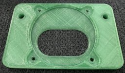
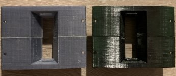
So the AMT mount prototypes are glued together. I printed two when I found out that my printer is not perfectly square, the third one was still not perfect, but the last one is. That is why they are not aligned perfectly. The rPET material could use a more powerful hot end than my printer currently has and maybe a slightly higher temperatire to be perfect, bit even now it is very strong and it seems it can be filled and sanded to a nice surface if needed.
For the next version, i will add buried M4 - M6 nuts for mounting the horn attachment closer to the opening.
Since the coverage is so narrow, I will try to design a 50x30 horn that would print on my 300x300 mm printer. It seems I could get around 300 mm depth from the mouth to the diaphragm with a single print.
The rPET is pretty strong, so I might get away with printing further to create a 600 mm wide horn with relatively thin walls. And since it is expanding, I might be actuall be able to print a bit wider than the bed size is, so I maybe could get to 700 mm wide horn, which should be large enough.
For the next version, i will add buried M4 - M6 nuts for mounting the horn attachment closer to the opening.
Since the coverage is so narrow, I will try to design a 50x30 horn that would print on my 300x300 mm printer. It seems I could get around 300 mm depth from the mouth to the diaphragm with a single print.
The rPET is pretty strong, so I might get away with printing further to create a 600 mm wide horn with relatively thin walls. And since it is expanding, I might be actuall be able to print a bit wider than the bed size is, so I maybe could get to 700 mm wide horn, which should be large enough
.Attachments
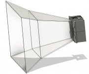
So this is the concept of the fully 3D printed horn front attachment. It seems it should be possible to print it on my printer with a spool of filament each including supports and strenghtening ribs. Since it is 3D printed, there is no reason for it to be flat like this. Ideally, I would like to generate a CD horn with ATH4 with the maximum dimensions my printer can take.
Attachments
But even
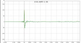
at low out put the distortion measurements is impressive, less than 1% distortion from a loudspeaker is not common.
The distortion is measured at 90 dB and one meter. The FR plots are 20 dB less. I had to take them at low level, these are just quick and dirty measurements after unpacking. For proper tests and listening, I need to buy some protection caps first. I am impressed by the impulse response, best I ever measured.
at low out put the distortion measurements is impressive, less than 1% distortion from a loudspeaker is not common.
Yes, and that is not with ideal measurement conditions.
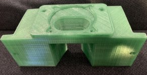
Yesterday I glued on the flanges to the horn attachment and and designed a short horn stub for building a cardboard horn mockup. My 34c9 project with 3FE22s will get the AL tubes polished properly, so I will have two drivers for first measurements if this will work or not.
Yesterday I glued on the flanges to the horn attachment and and designed a short horn stub for building a cardboard horn mockup. My 34c9 project with 3FE22s will get the AL tubes polished properly, so I will have two drivers for first measurements if this will work or not.
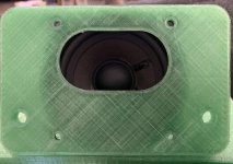
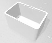
While driving home I realized I completely forgot about back covers for the 3FE22s! So the first one will be printed today to see if it fits as expected. It will be held by M6 threaded rods as the rest of the structure. The volume is around 0.6 - 0.7 l. Will be measured very scientifically by the amount of water it will hold
Attachments
Hi ! can you do a complete Cumulative Spectral-Decay plot maybe for all the tweeter working range ?... I am impressed by the impulse response, best I ever measured
anyway it would be telling to compare this impulse response with the one from a more conventional driver used to cover the same audio range. Maybe it is not that different ? usually dome mids/tweeters have big magnets and light diaphragms .... they are naturally fast. Settling time can be an issue ? ... maybe
Attachments
Last edited:
- Home
- Loudspeakers
- Multi-Way
- ESS AMT-1 in my projects